
Related Manuals for EVBOLT ASTEROPE 3


Summary of Contents for EVBOLT ASTEROPE 3
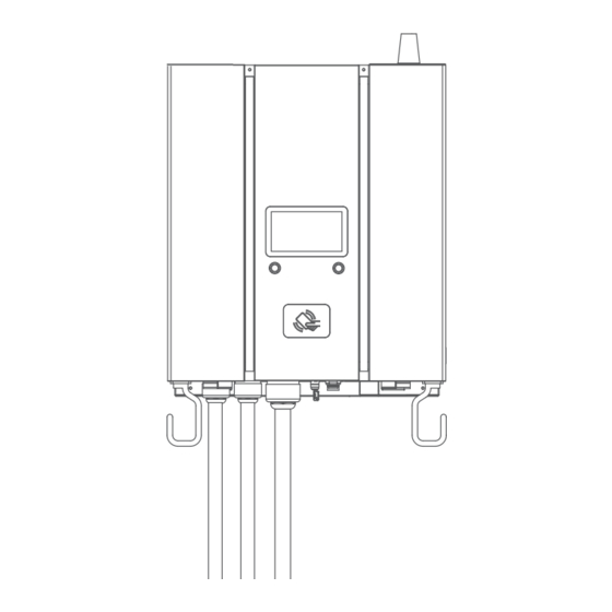
- Page 1 Electric Vehicle DC Charger ASTEROPE 3 Pedestal – Installation Manual Intellectual property of EVBOLT, Inc...
-
Page 2: Pedestal Dimensions
Pedestal Dimensions 60cm(23.62 in) 30cm(11.84 in) 15.2cm(5.98 in) 60cm (23.62 in) Unpack Intellectual property of EVBOLT, Inc Page 1 of 7... -
Page 3: Packing List
Installation STEP 1 Prepare a concrete base The concrete pad building should be compliance with regulatory and local code requirements. The following descriptions of the dimension or structure are minimum recommendation. Intellectual property of EVBOLT, Inc Page 2 of 7... - Page 4 Expansion screw hole is at least 11 cm.). Implantation ± 23cm conduit for input DC and Ethernet cables. 27.5 14.5 STEP 3 Screw 6 sets of expansion screws to the bottom of the stand as illustrated. Intellectual property of EVBOLT, Inc Page 3 of 7...
- Page 5 STEP 4 Mount 6 screws as illustrated below. STEP 5 Place the bottom plate as indicated below and then screw the four M12 expansion screws. Intellectual property of EVBOLT, Inc Page 4 of 7...
- Page 6 Screw 2 sets M4x10 screws and nut to the bottom of the stand. STEP 7 Position the bracket comes with ASTEROPE 3 wall mount charger as illustrated below, fasten with 4pcs M8xL12 screws marked in red. Intellectual property of EVBOLT, Inc...
- Page 7 According to the figure below, mount two M6 screws marked in red. STEP 9 Assemble the arms of the connector holder on both sides, fasten with 4 pcs of M8 screws for each arm. Intellectual property of EVBOLT, Inc Page 6 of 7...
- Page 8 Put on the connector base on both sides and fasten with 2pcs of M8 screws for each. STEP 11 Assemble the connector holders on both sides and fasten with 4pcs of M5 screws for each. Intellectual property of EVBOLT, Inc Page 7 of 7...
- Page 9 © 2022 EVBOLT INC. All Rights Reserved. Intellectual property of EVBOLT, Inc...
Need help?
Do you have a question about the ASTEROPE 3 and is the answer not in the manual?
Questions and answers