Subscribe to Our Youtube Channel
Summary of Contents for Rath SmartView 2100-SVCELLU
- Page 1 Installation & Operations Manual SmartView Cellular Gateway 2100-SVCELLU RP850001SVCELL N56W24720 N. Corporate Circle Sussex, WI 53089 Ver. 3 YEAR 800-451-1460 www.rathcommunications.com 08/2023 WARRANTY...
- Page 2 Thank you for purchasing RATH’s SmartView Cellular Modem. We are the largest Emergency Communication Manufacturer in North America and have been in business for over 35 years. We take great pride in our products, service, and support. Our Emergency Products are of the highest quality.
- Page 3 • RATH SmartView System ® • PC or Laptop to test the SmartView System • Battery backed up 120v power source or RATH RP7700104S ® • Standard size (25mm x 15mm) DATA ONLY SIM card • 2100-SVCELLU (AT&T, Verizon, T-Mobile, and Bell) NOTE: When activating SIM cards, IMEI of unit must be linked to SIM during SIM card activation.
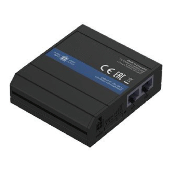
- Page 4 8. Using provided plug-in transformer, plug the 4-pin connector side into the “POWER” port on the cellular modem. 9. Connect the power brick from the plug-in transformer coming out of the enclosure to a standard 110vac wall outlet or RATH RP7700104S ®...
- Page 5 12. Wait 3 minutes for unit to fully boot. When fully booted, 4G LED should be illuminated along with at least 3 signal strength bars. If LEDs aren’t as described, see troubleshooting section for corrective action. NOTE: If less than 3 signal strength bars are illuminated, unit has low cell reception and will not function properly.
- Page 6 Troubleshooting Problem Possible Cause & Solutions Unit will not allow for • Verify both antennas are connected to the unit. web browsing: • Verify only “MOBILE” antennas are being used. • Verify both antennas are connected “MOBILE” port on gateway. •...
- Page 7 Wiring Diagram SMARTVIEW SYSTEM TO ANTENNAS MOBILE CELLULAR MODEM POWER TO 110VAC POWER Page 7...


Need help?
Do you have a question about the SmartView 2100-SVCELLU and is the answer not in the manual?
Questions and answers