
Related Manuals for Rath 2100-LTEGSM4


Summary of Contents for Rath 2100-LTEGSM4
- Page 1 Installation & Operations Manual 4G Cellular Gateway 2100-LTEGSM4 N56W24720 N. Corporate Circle Sussex, WI 53089 RP8500DCPR Ver. 1 800-451-1460 www.rathcommunications.com 09/20...
- Page 2 Thank you for purchasing RATH’s Cellular Gateway. We are the largest Emergency Communication Manufacturer in North America and have been in business for over 35 years. We take great pride in our products, service, and support. Our Emergency Products are of the highest quality.
- Page 3 2. Insert SIM card into J4 with the perforated edge first and the gold contact side facing downward. Push until you hear it click. 3. Screw in the antenna to J2 on the Cellular Gateway and ensure it is completely tightened. Note: Only use antennas approved by. RATH ® 4. Connect the battery to J3.
- Page 4 5. Connect the phone(s). The Cellular Gateway provides an RJ11 jack or hardwired screw terminals for connecting devices. RJ11 Jack: a. Take a male RJ11 phone line cord or plug it into the J1A jack on the Cellular Gateway. b. Plug the other end of the line cord into desired device. Hardwired Connection: a.
- Page 5 Note: Connect to RS232 (J10) or CANBUS (J8) to use as a data pass through. J2 - External Antenna- Connect the provided external antenna to the J2 connector. Only antennas approved by RATH should be used or the Cellular Gateway may not function properly and may be damaged.
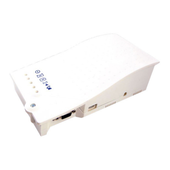
- Page 6 LED Indicators This Cellular Gateway has five indicator LEDs that constantly report the device status. The indicators will be red, amber, or green. Each indicator will be fully on, fully off, or flashing. The table below provides an overview of what each colored LED indicates: RUN LED FLASHING...
- Page 7 Wiring Diagrams Elevator Application Wiring Diagram: Antenna Traveling Cable Machine Elevator Room Single Pair 120vac Power Cellular Gateway Single Pair SmartRescue System Wiring Diagram: Antenna SMARTRESCUE PHONE DISCONNECT CALL TO RESCUE SmartPhone SERVICES RESCUE SERVICES SUB-MASTER 1 SUB-MASTER 2 2 Pair PHONE 1 PHONE 2 PHONE 3...
- Page 8 Command Center System Wiring Diagram: Two Wire Connection Command Center Antenna Two Wire Connection 1 Wire Pair (22/24 ga.) Single Cellular Pair Distribution Single Pair Gateway Module Two Wire Connection Power Cord Connection (Provided) Power Supply with UPS Two Wire Connection 120 Volt Power Connection to Incoming 120 Volt...
- Page 9 This Cellular Gateway includes a NiMh 800mAh battery that allows it to keep functioning in the event of a main power failure. The battery provides 4 hours of talk time. The battery should be replaced every 4 years. Only install batteries authorized by RATH and only allow qualified personnel to replace the battery. The battery should be properly ®...
Need help?
Do you have a question about the 2100-LTEGSM4 and is the answer not in the manual?
Questions and answers
Cellular gateway phone board is dead. Battery has 14v and I do have 120vAC feeding board, see pics,