Advertisement
Quick Links
Contents
Section 1
General Information
Section 2
Hardware
Section 3
Installation
Section 4
Wiring
Section 5
Management
Section 6
Features Overview
Section 7
Service Information
This manual applies to the following products:
•
RESMLAC 12EMG F35 (options)
Revision
Date
1
August 2022
RESMLAC 12EMG F35 - UM
Rugged IP67 Managed Ethernet Switch, with 12 gigabit port, all LAN ports
shared within two MIL-DTL-38999 connectors.
Modifications
Initial document
www.amphenol-socapex.com
IP67 rugged Ethernet Managed Switch
RESMLAC-12EMG-F35
- Hardware User Manual -
Page 3
Page 4
Page 5
Page 7
Page 12
Page 13
Page 16
rev. 1
Page 1/16
Tel: +33(0)4.50.89.28.00
Advertisement

Related Manuals for Amphenol Socapex RESMLAC-12EMG-F35

Summary of Contents for Amphenol Socapex RESMLAC-12EMG-F35
- Page 1 IP67 rugged Ethernet Managed Switch RESMLAC-12EMG-F35 - Hardware User Manual - Contents Section 1 Page 3 General Information Section 2 Page 4 Hardware Section 3 Installation Page 5 Section 4 Page 7 Wiring Section 5 Page 12 Management Section 6...
- Page 2 AMPHENOL SOCAPEX GENERAL CONDITIONS OF SALE (Effective as at 28th/09/2020) (EXTRACT) ARTICLE 11: GUARANTEE - LIABILITY 11.1. Products shall benefit from a legal guarantee of one year following the date of delivery in accordance with the terms and conditions indicated hereunder.
- Page 3 -45°C to +80°C and meet the toughest industrial and military environments such as MIL-STD-810F/G/GM, MIL-STD-1275, MIL-STD-461E up to the highest levels. The mentioned ability turns the RESMLAC-12EMG-F35 to the optimal solutions switch of choice for harsh environments constrained by space.
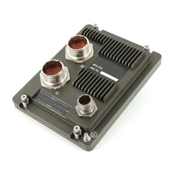
- Page 4 Front Panel The following describes the front panel, and LED indicators of the RESMLAC-12EMG- Display F35. LED Indicators The RESMLAC-12EMG-F35 unit has LEDs indications, • 1 LED - Power Indications • 24 LEDs – Ethernet Indications. The PWR LEDs is illuminated when input power is applied to the RESMLAC-12EMG- F35.
- Page 5 Refer to the mechanical drawings below. Make sure to allow enough room to route your Ethernet and power cables. The RESMLAC-12EMG-F35 weighs 1.150 Kg and is mounted via its four # 10-32UNF Captive Screws. The overall external dimensions of the RESMLAC-12EMG-F35 are 178(L) x 136(W) x 47(H) millimeters.
- Page 6 RESMLAC 12EMG F35 - UM rev. 1 Page 6/16 www.amphenol-socapex.com Tel: +33(0)4.50.89.28.00...
- Page 7 Section 4 Wiring Overview These switches provide connections to Ethernet devices in harsh environment. Typically, a port is used to connect to another Ethernet switch that is connected to the main Ethernet backbone. The other Ethernet ports are then connected to Ethernet devices such as communication systems, Ethernet I/O, or industrial computers.
- Page 8 Ethernet plug Pinout for J2 connector wiring RESMLAC 12EMG F35 - UM rev. 1 Page 8/16 www.amphenol-socapex.com Tel: +33(0)4.50.89.28.00...
- Page 9 Pinout for J3 connector Ethernet ports The following table indicates the appropriate wiring connections for the Gigabit Ethernet connection ports relative to the available link speeds. Please note that MDI is the preferred connection choice. The Ethernet switches are capable of connecting using the MDIX scheme, but it is not advised.
- Page 10 Serial wiring To manage the switch via the WEB interface you can use all tweve ports. You can access the CLI mode via port MNG through serial link. The following table indicates the appropriate wiring connections for the serial port, spread among J2 connector.
- Page 11 Tooling The plugs are using crimp contacts. We suggest using hereunder tooling. Crimping tools Amphenol No Military No Crimping tool 809 801 M22520/2-01 Positioner 809 835 M22520/2-07 Plastic insertion and Contact size Amphenol No Military no removal tools 809 856 M81969/14-01 Backshell We suggest using TV35 backshells with corresponding heat shrinks.
- Page 12 Section 5 Management Management The switch is managed. It can be accessed either using the web interface or using RS-232 console port (shared among J2 connector, see Serial Wiring for details). For in-band Ethernet management configuration use either one of the 12 ports. management Configure your computer with compatible IP address and access to the switch using a web browser.
- Page 13 Section 6 Features Overview Switching Here’s a brief explanation of some of the features found in these switches documented by Features this manual. ETHERNET PORTS • 12 x switched 10/100/1000 (Gigabit Ethernet) ports STANDARDS COMPLIANCE • IEEE 802.1x MAC based Authentication •...
- Page 14 PERFORMANCE • 26.8 Mpps wire speed forwarding rate • 20 Gbps maximum forwarding bandwidth • 8K MAC Address CHASSIS • Machined rugged aluminum • Conductively cooled w/custom internal heat-sinks • Ingress protection against sand, dust and moisture • Anodize Coating, MIL-A-8625, Type II, Class 2 POWER •...
- Page 15 INSTALLATION • Set of Four # 10-32UNF Captive Screws for mounting to any flat surface. COOLING • No Moving Parts. Passive Cooling OPERATING TEMP • -45ºC to +80ºC (-49ºF to +176ºF) – Cold Start-Up STORAGE TEMP • -45ºC to +85ºC (-49ºF to +185ºF) RESMLAC 12EMG F35 - UM rev.
- Page 16 Section 7 Service Information We sincerely hope that you never experience a problem with any Amphenol product. If you Service do need service, call Amphenol at +33(0) 450 89 28 00 and ask for Applications Information Engineering. A trained specialist will help you to quickly determine the source of the problem.
Need help?
Do you have a question about the RESMLAC-12EMG-F35 and is the answer not in the manual?
Questions and answers