Table of Contents
Advertisement
Quick Links
Questa scheda può essere utilizzata solo con drive ADV200 versione firmware 3.0 e successive
This card can be used only with drive ADV200 firmware version 3.0 and later
Isolamento funzionale - Functional insulation
FELV (Functional Extra Low Voltage) EN 61800-5-1
Introduzione / Introduction
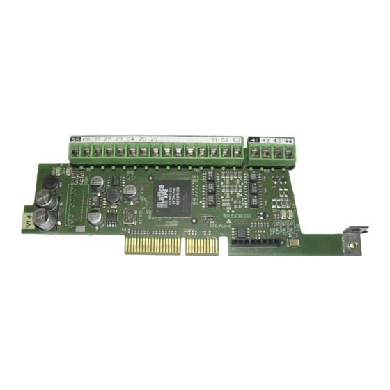
Scheda di espansione per un ingresso / uscita encoder digitale optoisolato TTL/
HTL per i drive ADV200.
E' possibile montare fino a due schede encoder per Drive, per maggiori dettagli
vedere il capitolo 5.4 del manuale ADV200 Guida Rapida all'installazione.
Gli ingressi Freeze congelano la posizione encoder e sono utilizzati solo da MDPlc
The card adds 1 digital TTL / HTL optocoupled encoder input / 2 freeze inputs / 1 output to
the ADV200 drive.
It's possible to mount up to 2 encoder cards for each drive; for more details see chapter 5.4
of ADV200 Quick Start Up
The Freeze inputs store the encoder position and can be used only by MDPlc.
Fissaggio / Mounting
Fare riferimento al capitolo Installazione schede opzionali del manuale
ADV200 Guida rapida all'installazione.
Refer to ADV200 Quick Start up manual, chapter Installation of optional cards.
Importante!
Attention!
_________________________________________________________________________
Guide.
ATTENZIONE: Utilizzare solo le viti in dotazione !
CAUTION: Use only the supplied screws !
Possono essere inserite fino a tre schede opzionali nei tre alloggiamenti
(Slot) che si trovano sotto la copertura superiore:
• Slot 1: dedicato alle schede IO (EXP-IO-...-ADV) (*)
• Slot 2: dedicato alle schede Encoder (EXP-...-ADV)
• Slot 3: dedicato alle schede Bus di campo (EXP-PDP-ADV, EXP-CAN-ADV,
ecc) (*)
Up to three optional cards can be inserted in the three slots under the top
cover:
• Slot 1: dedicated to IO cards (EXP-IO-...-ADV) - (*)
• Slot 2: dedicated to Encoder cards (EXP-...-ADV)
• Slot 3: dedicated to field Bus cards (EXP-PDP-ADV, EXP-CAN-ADV, etc.)(*)
(*) Nel caso sia necessario gestire 2 o 3 encoder, in questi Slot possono essere inserite anche le
schede per gli encoder digitali (EXP-DE-I1R1F2-ADV e EXP-DE-I2R1F2-ADV), vedere il capitolo
11.5.1 del manuale ADV200 Guida rapida per maggiori dettagli.
(*) If managing 2 or 3 encoders, these slots can also be used for the digital encoder cards (EXP-
DE-I1R1F2-ADV and EXP-DE-I2R1F2-ADV), see section 11.5.1 ADV200 Quick Start up manual,
for further details.
Se viene inserita una scheda opzionale in uno Slot errato, il drive segnalerà
un messaggio di errore.
If an optional card is inserted in an incorrect Slot, the drive will send an
error message.
Encoder expansion card S5L30
• 1 TTL/HTL Encoder Input
• 1 TTL/HTL Encoder Output Repetition
• 2 Channel freeze
ADV200
Instruction manual
EXP-DE-I1R1F2-ADV
Digital Incremental (DE)
1
Advertisement
Table of Contents

Subscribe to Our Youtube Channel
Related Manuals for gefran EXP-DE-I1R1F2-ADV

Summary of Contents for gefran EXP-DE-I1R1F2-ADV
- Page 1 • Slot 3: dedicated to field Bus cards (EXP-PDP-ADV, EXP-CAN-ADV, etc.)(*) (*) Nel caso sia necessario gestire 2 o 3 encoder, in questi Slot possono essere inserite anche le schede per gli encoder digitali (EXP-DE-I1R1F2-ADV e EXP-DE-I2R1F2-ADV), vedere il capitolo 11.5.1 del manuale ADV200 Guida rapida per maggiori dettagli.
- Page 2 (1) The internal power supply of the encoder can be selected from the keypad (ENCODER CONFIG menu, PAR 2102 Encoder supply) with minimum step 0.1 V (2) Consider the possible voltage drop due to the length of the cable when you set the supply voltage. Encoder option type EXP-DE-I1R1F2-ADV 5.2 V 5.2 V 20.0...
- Page 3 Leds Green Indica che l’espansione è alimentatata ed attiva The led is ON when the expansion card is powered and The led is ON when the encoder is powered Green Indica che l’encoder è alimentato Led di diagnostica. Diagnostic LEDs.. Yellow Se l’encoder è...
- Page 4 Schemi / Diagrams Fig.1: Incremental Digital Encoder (DE) - PUSH-PULL / LINE DRIVER +VE out 0VE out DI - CM DI - F1 DI - F2 Fig.2: Incremental Digital Encoder (DE) SINGLE ENDED NPN O.C. +VE out 0VE out DI - CM DI - F1 DI - F2 _________________________________________________________________________...
- Page 5 Fig.3: Incremental Digital Encoder (DE) SINGLE ENDED PNP O.C. +VE out 0VE out DI - CM DI - F1 DI - F2 Fig.4: Incremental Digital Encoder (DE) - PUSH-PULL / LINE DRIVER (Con alimentazione esterna / With external supply) DI - CM DI - F1 DI - F2 _________________________________________________________________________...
- Page 6 Fig.5: Incremental Digital Encoder (DE) SINGLE ENDED NPN O.C. (Con alimentazione esterna / With external supply) DI - CM DI - F1 DI - F2 Fig.6: Ripetizione Encoder - Repeat Encoder A+ out A- out B+ out B- out Collegamento schermatura, vedere figura 5.2.3.1 del manuale ADV200 Guida Rapida. Connection of shielding, see figure 5.2.3.1 on ADV200 Quick Start _________________________________________________________________________ ADV200...
- Page 7 Dati tecnici / Technical data TTL Line-driver A+ A-, B+ B-, Z+ Z-, differenziali line driver, A+ A-, B+ B-, differential line drivers, Canali / Channels optoisolati. optoisolated. Gestita mancanza segnali encoder. Management of loss of encoder signals 200 kHz (verificare il numero di impulsi 200 kHz (check the number of encoder Frequenza max.
- Page 8 Tipo scheda / Card type Nessuna / None 1544 Enc 1 EXP-DE-I1R1F2-ADV 2056 Enc 7 EXP-DE-I2R1F2-ADV 1800 Enc 2 EXP-SE-I1R1F2-ADV Enc 3 EXP-SESC-I1R1F2-ADV Enc 4 EXP-EN/SSI-I1R1F2-ADV 1032 Enc 5 EXP-HIP-I1R1F2-ADV Sconosciuta / Unknown Manuale EXP-DE-I1R1F2-ADV -IT/EN Rev. 0.4 – 2-12-2020 1S9G74 _________________________________________________________________________ ADV200...
Need help?
Do you have a question about the EXP-DE-I1R1F2-ADV and is the answer not in the manual?
Questions and answers