Advertisement
Quick Links
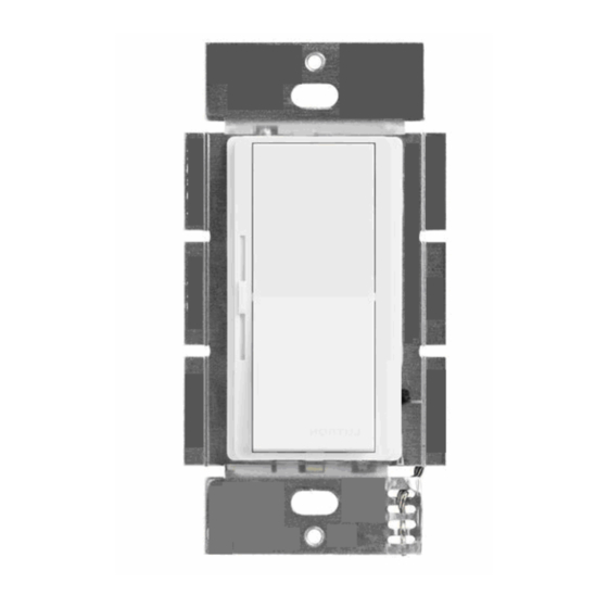
AL-WS-DR2
Decorator style Switch/Driver
Dual Constant Current
Tunable White with Fade
56 watt
CV and CC autodetect
12 volt Fan direct drive
Left Slider
Product Description - AL-WS-DR2 wall switch
This switch operates just like any standard residential light switch – however it takes
24-54v DC instead of 120VAC, and directly drives up to 56 watts of LED bulbs. This
Decorator style switch in a standard residential style outline fits into any home, looks
like any switch yet meets NEC article 411 for Low Voltage lighting.
It supports fixed color temperature or tunable white LED fixtures for time of day light
controls. With tunable white, it supports dim to warm.
Stand alone it operates as a simple switch for 2 strings of LED's. Jumper selections
for 2 channels with 300, 360, 660 or 720 mA for up to 30 watts per channel. For
example, 10 x 6 Watt LEDs can connected, 4 in series to each of the 2 outputs on this
switch / dimmer device. Use AWG 16 or 18 to bring 48v ( or 24 to 54 volts ) from a
central power supply over to the switches, then use AWG 20 to connect to your LEDs
– no crimping tools are required to wire this device.
For 3-way operation – a simple 2 wire link with AWG24 or better allows 2, 3, or an
unlimited numbers of switches to control one set of LED's. Any single pole switch
found at Home Depot can be used to add a 3-Way remote switch, or the AL-WS-M
momentary switch can be used for unlimited 3-Way connections.
A proven mechanical switch and brightness slider leverages mass production of
Decorator switches, now for low voltage applications – a casual user requires no
training, no App to use this switch. Perfect, flicker free dimming from off to 0.1% to
100%. No network setup is required.
To enable Home / Business automation – the AL-WS-DR2 includes a DALI opto
isolated serial bidirectional port for remote and voice control. Use the AL-DALI-Pi Hub
to connect to Alexa or Google home voice control. The DALI protocol is supported,
with automatic addressing. Use low cost wire in uncomplicated topology to implement
remote management. Power and DALI have in and out connectors to avoid wire nuts.
Connect 24 volt strip lights up to 15 watts per side, or connect a 12 volt DC Fan with
up to 12 watts.
3-Way
DALI
ATX LED Inc
1108 Lavaca St Ste 110, #489
Austin Tx, 78701
512 377 6052
512 377 6052
512 377 6052
512 377 6052
http://atx-led.com
1
Advertisement

Related Manuals for ATX LED AL-WS-DR2

Summary of Contents for ATX LED AL-WS-DR2
- Page 1 App to use this switch. Perfect, flicker free dimming from off to 0.1% to 100%. No network setup is required. To enable Home / Business automation – the AL-WS-DR2 includes a DALI opto isolated serial bidirectional port for remote and voice control. Use the AL-DALI-Pi Hub to connect to Alexa or Google home voice control.
- Page 2 Specifications Spring loaded connectors ( 2 pairs ) Power source and Pass Thru for AWG 16-20 wire 300 mA base current, jumper options for 360, LED constant current output 660 or 720 mA per channel Spring loaded connectors ( 2 pairs ) Diiming range 100 uA to 660 mA, 3000 steps Input voltage range...
- Page 3 Wiring the AL-WS-DR2 for up to 8 fixed LEDs Wiring the AL-WS-DR2 for 1 to 4 CCT LEDs Powering the AL-WS-DR2 the first time Power the switch via either of the 2 power input connectors, 44 to 54v is recommended. No DALI connection is required.
- Page 4 Dimming is via the slider, Color temperature control occurs with the switch pushed moving the slider at the same time. Many advanced features require the ATX LED Hub to set the features – after which the ATX LED Hub can be removed again –...
-
Page 5: Related Products
AL-WS-DR2 Versions 2023 2020 2018 2019 Tunable CCT Tunable CCT Fixed CCT Fixed CCT low dim low dim low dim Diagnostics+Topology Diagnostics Related Products Model LED mode DA Bus N-Way AL-WS-DR2 Auto Detect CCT Exhaust Full Operation Full AL-WS-DR2C CCT Selector... -
Page 6: Wiring Example
View the wiring guide before wiring https://atxled.com/How2/ Wiring example Basic Connection 8 Fixed LEDs or 4 CCT with 6 watts each LEFT RIGHT Cool White Warm White or Fan Power the switch via the Power input connectors, 51v is recommended. 44-54 volts is the range. For 5 fixture applications, a 54v supply is required. - Page 7 Light Switch operation – Momentary style A momentary switch springs back to On when the lever is pressed down, an On/Off does not spring back (On/Off see below) When installing a momentary switch type - the slider is on the left, LED outputs on the bottom. Function Press How to trigger...
- Page 8 Do not hold longer than 45 seconds. Upon release the level will be stored and is normally not the same level as the slider on the main switch. If a AL-WS-DR2 with a momentary switch is operating in On/Off style – Setting Momentary Style 5 times then press the rocker 5 times briefly –...
- Page 9 “N-Way” wire input connection – Hardware Options The N-Way input has several functional options. The default is simple 3-Way. Other options are enabled by DALI commands – see below. Many 3-Way Push Buttons in parallel With the Push Button method – a momentary switch like the AL-WS-M or RH-253 switch can be used. Each momentary action on the N-Way pin will toggle the light on / off.
-
Page 10: Timer Functions
A simple Normally Open door alarm switch can be wired to the N-Way input. The current is low so there will be no damage to the contact. Thus – when the door opens – the light will go on. On first installation, the AL-WS-DR2 will require 60 seconds after the door is closed the first time to recognize the contact, after that, the operation mode will be saved. - Page 11 Default DALI Operation By default – the AL-WS-DR2 only responds to DALI broadcast commands – it will not transmit. There is no group or short address assignment. Since the device accepts DALI broadcast commands – any DALI switch or master that sends broadcast commands can connect to this device remotely for on/off/dimming –...
- Page 12 ZWD Management Screen...
- Page 13 DALI commands also are used to determine the 3-Way state. Therefore, a DALI command with the matching Group or Individual as the AL-WS-DR2 address will set the attached lights on or off – and all local switches – physical or virtual – will reflect that change – so that the next flip of any switch will turn the light off or on as intended.
- Page 14 Fade seconds CCT fade The AL-WS-DR2 supports slow CCT fade – with 3000:1 dimming, precise and seamless fading looks fantastic, and operates autonomously – no hub is required. CCT fade is from 0 to 2550 seconds. This allows smooth color changes at evening for example.
- Page 15 DALI bus. The result allows unlimited numbers of switches to dim and control a common light. Since each AL-WS-DR2 or AL-WS-010v device supports the N-Way input – the number of control points is limitless.
- Page 16 Disabled No action The AL-WS-DR2 can have this 2 DALI address assigned to the Warm/Fan output. This could be either the fan or a single color LED. See notes in the LED driver section. The device will operate as follows:...
-
Page 17: Auto Detection
In this mode, both outputs will have the same level. Move the slider to control brightness. If the number of LEDs is the same on both sides, the AL-WS-DR2 will default to CCT mode ( and appear as ½ brightness) – use the ZWD configuration tool to force fixed mode. - Page 18 24v operation. FAN drive mode An attached ATX LED 12v fan on the Right side, with it’s 4000 uF capacitor will be auto detected, the DR2 will enter Fan mode automatically. An attached AXT LED 48v fan on the Right side will be autodetected and the DR2 will enter Fan mode automatically.
- Page 19 Dual LED current drivers, Fan voltage Driver The AL-WS-DR2 has two multi mode drivers built in. CCT, Fan + Light and Fan-Only modes are automatically detected. Using the Dali memory write commands, any of these operational modes can be selected.
- Page 20 Exhaust Fan and Light Configuration ZWD configuration settings...
- Page 21 Exhaust Fan and Light Configuration and wiring Intended for exhaust fans, the Left output can be a dimmable light, the Right driver powers the fan.. The main switch and DALI control the light. A 2 address can be configured for DALI control of the fan independent of the light.
- Page 22 Fan + LED Operation with N-Way When an LED is connected on the left/Cool side, the main switch controls that light, and an optional external switch controls the Fan. The times shown below can be changed by the DALI hub. Either a rocker style or momentary style switch can be used to control the fan.
- Page 23 The ohms was high – the ohms calculated is stored Normal operation – the ohms per chip is stored In 2019 and later hardware – the power reported assumes a 660 mA LED is attached; the AL-WS-DR2 measures how many LEDs are connected and performs the correct power calculation.
-
Page 24: Troubleshooting
Use the ATX LED Hub “pulse all” feature to verify that all devices are connected to the DALI bus Use the ATX LED Hub / Advanced / Query DALI Power Status to verify that the DALI bus has 15 to 17 volts and no... - Page 25 Recommended ETL and UL listed LED’s 51v power supply Size Total power rated Type Model inches LED rating output Watts Note watts Count 51v input Flat Ceiling P023R6 3 / 5 660 mA 2x 4 series Flat Ceiling P023R6 CCT 3 / 5 660 mA 4 in series...
- Page 26 Recommended ETL and UL listed LED’s 54v power supply Size Total power rated Type Model inches LED rating output Watts Note watts Count 54v input Flat Ceiling P023R6 3 / 5 660 mA 2x 5 series Flat Ceiling P023R6 CCT 3 / 5 660 mA 5 in series...
- Page 27 DALI Commands Supported Notes: * means must be sent twice in 100ms, A = ATX LED enhanced commands Individual Short Address Commands Individual Short Address Commands Individual Short Address Commands Individual Short Address Commands LED Off UP 8 steps Down 8 steps...
- Page 28 DTR Lockout feature If the AL-WS-DR2 detects any DTR set functions on the bus, it will block any DALI transmit commands for 200ms. Since DTR commands are often part of a sequence of DALI commands, this lockout prevents any ATX LED device from sending any command that can interfere with a that sequence.
-
Page 29: Memory Bank
Serial Number Assigned by Master Serial Number Serial Number – lsb N-Way Mode Read/Write See details 17-63 Storage User Defined UPC Codes: 722512407176 AL-WS-DR2 (2018) 722512407183 AL-WS-DR2 (2019) 784099948268 AL-WS-DR2 (2019) 784099948190 AL-WS-DR2 (2020) 784099948190 AL-WS-DR2 (2023) 784099948206 AL-WS-DR2C v4... - Page 30 Memory Bank 1-3 (DTR1 = 1,2,3) DTR register Name Value Bytes per Bank ( minus 1) Checksum calculated Number of Banks ( minus 1) 3-63 User Storage Memory Bank 4 real time data (DTR1 = 4) DTR register Name Value 3, 4 Up Time lsb (3) msb (4) Hours...
- Page 31 Read/Writable Memory Bank 5 (DTR1 = 5) Transmit Group 0-15 means send group 255 means send short address Right Max Voltage Volts 9-54 Left Max Voltage Volts 9-54 0 = Auto and calibrate 1 = Fixed Split 2 = Led plus 12v FAN Driver Operation mode 3 = CCT 4 = Fixed match left=right...
- Page 32 Read Only Diagnostics in Memory Bank 5 (DTR1 = 5) CCT_Level 0-100 Ratio of Left to Right outputs N Way Mode See command 35 1=local off 2=local on Last Control 4=DALI off 5=DALI on 24/25 High Power converter minimum 26/27 LSB/MSB mVolts Right, Left...
Need help?
Do you have a question about the AL-WS-DR2 and is the answer not in the manual?
Questions and answers