Advertisement
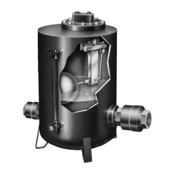
YARWAY CONDENSAVER™ SERIES STEAM CONDENSATE RETURN PUMPS
INSTALLATION, OPERATION AND MAINTENANCE INSTRUCTIONS
Before installation, these instructions must be carefully read and understood.
INSTALLATION
The unit should be installed in a level position.
Follow the piping arrangement of Figure 1 for
a vented receiver application or Figure 2 for a
pressurized receiver application.
Upstream piping must always be equal to or
larger than the check valve connection size
and block valves must be full ported to achieve
rated capacities. The pump should not be used
to support the weight of the piping.
To prevent water hammer and damage to
the pump's outlet check valve when lifting
condensate large heights, install a check valve
at the highest point of the return line.
Vented Receiver and Pressurized Receiver
To prevent upstream equipment flooding
while the pump is discharging, a condensate
receiving vessel should be installed directly
above the CondenSaver™ Series with the
necessary filling head distance between the
bottom of the receiver and the top of the pump.
Emerson.com
FIGURE 1
Vented Receiver Application
Atmospheric Vent
Condensate
Vented Receiver
Filling Head (In.)
Inlet Lift
Check Valve
FIGURE 2
Pressurized Receiver Application
Condensate from
Steam Traps
Pressurized System
Filling Head (In.)
Inlet Lift
Check Valve
© 2024 Emerson. All Rights Reserved.
Motive Pressure
Pump Exhaust
Drip Trap Use
with Steam Only
To Drain or Vent
Outlet Lift
Check Valve
Pressure Driven
Pump
Motive Pressure
Pump Exhaust
Drip Trap Use
with Steam Only
Outlet Lift
Check Valve
Pressure Driven
Pump
Return Line
Pressure
Return Line
Lift Pressure
(Ft. X 0.4333)
Return Line
Pressure
Return Line
Lift Pressure
(Ft. X 0.4333)
Process Steam Trap
FCIM-20083-EN 24/02
Advertisement
Table of Contents

Summary of Contents for Emerson YARWAY CONDENSAVER Series
- Page 1 CondenSaver™ Series with the Inlet Lift Outlet Lift Check Valve Check Valve necessary filling head distance between the Process Steam Trap Pressure Driven bottom of the receiver and the top of the pump. Pump Emerson.com FCIM-20083-EN 24/02 © 2024 Emerson. All Rights Reserved.
- Page 2 YARWAY CONDENSAVER™ SERIES STEAM CONDENSATE RETURN PUMPS INSTALLATION, OPERATION AND MAINTENANCE INSTRUCTIONS COMMISSIONING MAINTENANCE REASSEMBLY 1. Open the motive pressure line block valve. The Yarway CondenSaver™ Series does not 1. Install the new valve bodies. The body with If steam, ensure that the steam trap require frequent service.
- Page 3 YARWAY CONDENSAVER™ SERIES STEAM CONDENSATE RETURN PUMPS INSTALLATION, OPERATION AND MAINTENANCE INSTRUCTIONS FIGURE 3 PARTS ORDERING Pump Mechanism Quick Change Kits include Items 1 to 19 PARTS LIST Item Description Float Float Arm Rear Link Spring End Cap Compression Spring Spring Arm Inlet Valve Assembly Exhaust Valve Assembly...
- Page 4 Use protective devices. Wash hands thoroughly after contact with dust before eating or smoking. FCIM-20083-EN © 2024 Emerson Electric Co. All rights reserved 02/24. Yarway is a mark owned by one of the companies in the Emerson Automation Solutions business unit of Emerson Electric Co. The Emerson logo is a trademark and service mark of Emerson Electric Co. All other marks are the property of their prospective owners.


Need help?
Do you have a question about the YARWAY CONDENSAVER Series and is the answer not in the manual?
Questions and answers