
Related Manuals for MettaX MC908 MDVR

Summary of Contents for MettaX MC908 MDVR
- Page 1 User manual MC908 MDVR (4CH&8CH) Important: Read Before Installation Please take a moment to carefully review and understand the following information before proceeding with the installation of the device.
-
Page 2: Table Of Contents
Contents 1. Product introduction......................6 2. Notice..........................7 3. Product Specifications ....................8 4. Definition of accessories and interfaces..............11 4.1 Inspection of products and accessories..........11 4.2. Panel introduction................12 4.3. Interface definition................12 5. Installation instructions....................14 5.1. Hard disk, SD card, SIM card...............14 5.2. Antenna installation................15 5.3 Debug screen connection..............15 5.4. - Page 3 6.3. User login for the configuration system..........21 6.4. Enquiry....................22 6.4.1 Video search................22 6.4.2 Log query................23 6.4.3 Image search.................23 6.5. System settings..................24 6.5.1 Registration information............24 6.5.2 Menu settings.................25 6.5.3 Account management............26 6.5.4 System clock................26 6.5.5 Power management.............28 6.6. Record settings..................29 6.6.1 Basic settings................29 6.6.2 Video output................29 6.6.3 Transcode settings..............30 6.6.4 Time recording...............31...
- Page 4 8.4 WIFI Setting....................38 8.5 FTP Setting....................39 9. Alarms and peripherals....................40 9.1 IO alarm....................40 9.2 Speed alarm..................41 9.2.1 Speed setting.................41 9.2.2 Alarm settings.................42 9.3 Vehicle status alarm................42 9.3.2 Alarm settings.................43 9.3.3 Installation direction..............44 9.4 Detection....................44 9.5 AI Setting....................45 9.5.1 Built in AI-algorithm software..........45 9.5.2 DMS/ADAS................46 9.5.3 BSD...................47 9.5.4 Mode selection..............47...
- Page 5 10.6 Serial port test..................51 11. Equipment maintenance....................52 11.1 Power ON / Power OFF..............52 11.2 Parameter management..............52 11.3 Disk.......................53 12. Platform connection....................54 13. Troubleshooting of common problems..............56...
-
Page 6: Product Introduction
Product introduction The device is an intelligent terminal product that combines various advanced features such as GPS/Beidou positioning monitoring, local SD card recording, 4G remote real- time video surveillance, IP voice, DMS/ADAS/BSD, and more. It seamlessly integrates real-time monitoring, production operation management, command dispatch, and other functionalities. -
Page 7: Notice
Notice In order to ensure the safe use of the device and extend the service life of the equipment, the user should fully consider the following factors during installation: 1) After receiving the product, please check the packages of the device and accessories in time. -
Page 8: Product Specifications
Product Specifications PARAMETER ITEM Language English Linux Graphic menu operation interface (OSD menu), character Operation interface superposition function Support mouse and remote control operation to set system parameters ARM Cortex CA9 Duel Core@1.4GHz Processor and CPU Memory 1GB DDR3 4 CH CVBS,1.0Vp-p, 75Ω 8 CH CVBS,1.0Vp-p, 75Ω... - Page 9 Alarm input 6-CH input 1-way output, linkage sound and light alarm, oil and power Alarm output cut, etc. 1*USB interface 1*RS232 interface, which can expand to connect the ID card reader, oil sensor, etc. communication interface 1*RS485 interface,expand to connect PTZ 1*10M/100M Adaptive network interface,Support TCP / IP, FTP, DDNS network protocol.
- Page 10 Lane departure, Pedestrian detection, vehicle distance ADAS detection, etc. AI Functions Fatigue driving test, smoking, and unsafe driving habit detection. Left blind spot detection, right blind spot detection Adaptive wide power input, with overload, under voltage, Power short circuit, reverse connection and other protection management functions;...
-
Page 11: Definition Of Accessories And Interfaces
Definition of accessories and interfaces 4.1 Inspection of products and accessories Before using this product, please check whether the product is damaged and whether the accessories are complete. If there is any missing, please contact your supplier. The lists of products and accessories are as follows: Table 1. -
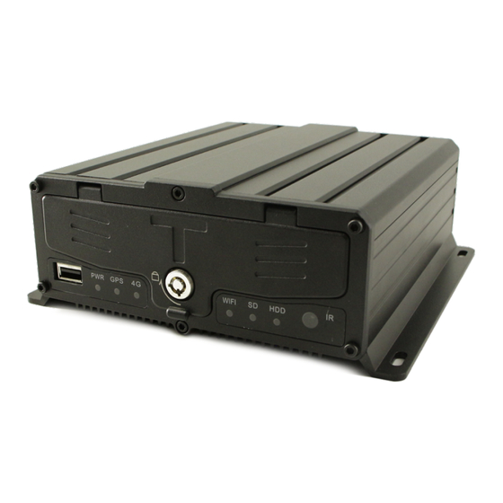
Page 12: Panel Introduction
AV-IN(6-core) AV-OUT(4-core) 4.2 Panel introduction Chart 1. Front Chart 1. Front 4.3. Interface definition This paper mainly introduces the definition of power supply, I / O, audio and video... - Page 13 interfaces, as follows: 1) Definition of power interface Chat 3. Definition of power interface 2) I / O interface definitions Chat 4. 24PIN 3) Definition of audio and video interface Av-in1 ~ 4 camera interface Av-in5 ~ 8 camera interface Av-out display interface...
-
Page 14: Installation Instructions
Installation instructions 5.1. Hard disk, SD card, SIM card To start, use the provided key to unlock and open the front panel cover. Once opened, you will find the interface of the SIM card, hard disk box and SD card, as illustrated in the diagram below. -
Page 15: Antenna Installation
5.2. Antenna installation Please correctly connect the 4G and GPS antennas. To achieve optimal positioning performance, the receiving surface of the GPS antenna must face upwards with no metallic objects above it. The bottom of the antenna should be flat, and its tilt angle should not exceed 30 degrees. -
Page 16: Adas/Dms Installation And Debugging
5.5.ADAS/DMS Installation and debugging 5.5.1 DMS Installation 1) Installation position: A-pillar of the cab 2) Installation Height requirements: 10-15cm below the horizontal line of driver's eyes (the camera should have a slightly inclined upward angle to look up at the driver's eyes, which is better for fatigue detection). -
Page 17: Power Connection
5.6. Power connection 1)Connect the power to the device according to the definition of power line interface. Before connecting, please check the connected power supply voltage, which should be in the range of 9-36V, The recommended operating voltage is 12V or 24V to prevent the equipment from abnormal due to voltage mismatch. -
Page 18: Product Firmware Upgrade
5.8. Product Firmware upgrade 1) First, put the upgrade software into SD card / U disk; 2) Insert SD card / U disk with upgrade file; 3) Enter the system menu "system information" to view the application program and MCU version number; 4) The upgrade version number should be different from the device current version number, and the device will be upgraded automatically if the USB flash disk or SD card is inserted;... -
Page 19: System Main Menu Operation Instructions
System Main Menu Operation Instructions 6.1. Infrared remote control key description Button Description Main Device This machine has no remote control shutdown function. Press login to log in to the main page (operation of Power cable main menu interface). [0-9] key: in the setting state, the number input key is used to select numbers. -
Page 20: Text Input Instruction
In the state of device information, you can go to the serial port test interface. In the state of device information, you can go to the INFO automatic test interface. When install PTZ camera, adjust the camera through this button. 6.2. -
Page 21: User Login For The Configuration System
2) Operation by Remote control Step 1: Using the four arrow buttons on the remote control, move the cursor to the the menu. And press ‘OK’ to the menu. After the above steps are completed, press "exit" key to return, and then save it. For other menu text input, and so on. If you encounter errors in the input process, please press "Dec"... -
Page 22: Enquiry
6.4. Enquiry The query menu includes: video search, picture search and log query. 6.4.1 Video search Search date: press the number key to enter the date, the default time is the current day. Start time: press the number key to enter the time, and the default value is 00:00:00. End time: press the number key to enter the time, and the default value is 23:59:59. -
Page 23: Log Query
Press the direction key to select the video data to be viewed, check the file, select the playback key to start playing the video data, and press the [exit] key to return to the previous menu. Press the direction key to select "home page", "previous page", "next page" and "last page", press the [OK] key to display the page turning information, and click export video file to U disk. -
Page 24: System Settings
6.5. System settings The system settings menu includes: registration information, menu settings, account management ,time settings, and power settings (Parameter configuration and modifications need to be saved before taking effect). 6.5.1 Registration information 6.5.1.1. Device information: Device ID: the device ID is used for cloud platform device ID. -
Page 25: Menu Settings
6.5.1.3 Standard Terminal model: fill in the terminal model License plate color: license plate color selection Terminal ID: fill in the ID number of the terminal. Province ID: fill in the province ID of the vehicle. Factory ID: fill in the Factory's ID number. City ID: fill in the city ID of the vehicle. -
Page 26: Account Management
6.5.2.2 Layout: set the zoom width, height and X, y offset position information of the device menu page. 6.5.3 Account management When the password enable is activated, both regular users and administrator users are required to use a password to log into the system's main menu. 6.5.4 System clock This menu is used to sets parameters ,such as the device date and time. - Page 27 6.5.4.1 Basic settings(Format):Date format: different date formats can be selected 6.5.4.2 Time synchronization (Sync) Date: enter the date of the day by number Time: manually input the current time according to the number Time zone: you can set the time zone where the device is located Time synchronization: optional timing mode: GPS, NTP, etc 6.5.4.3 Summer time (DST) When DST is turned on, the date and time will be refreshed according to daylight...
-
Page 28: Power Management
6.5.5 Power management 6.5.5.1 Switch On and Off Power mode: press the number key to select the type. The default is ignition mode, which can be set to timing mode. Power off Delay: Main power, standby power delay shutdown ": press the number key to enter the time, the default is 1 minute, can be set to 1-14400 minutes. -
Page 29: Record Settings
6.6. Record settings The record setting menu includes: video input, video output, bitstream setting, IPC setting, timing recording and storage setting, PTZ setting. 6.6.1 Basic settings Video format: select PAL / NTSC according to the image format of the camera, and restart automatically after saving the changed format. -
Page 30: Transcode Settings
6.6.2.2 Preview OSD Set preview interface display: channel name, video status, video status and resolution, GPS, time, alarm, customized X, Y coordinates 6.6.3 Transcode settings 6.6.3.1 Main stream Enable: turn on or off channel recording function. Resolution: 5 video resolutions can be selected:D1, HD1, CIF, 720P, 1080P Frame rate: the channel video frame rate of 1-25 frames can be selected. -
Page 31: Time Recording
6.6.3.2 Sub stream Resolution: can be set to D1, HD1, VGA, CIF Frame rate: 1-25 frame rate can be selected. Picture quality: set the level of picture quality, you can choose the level of 1-8. Shortcut option: the resolution of 4-channel cameras can be set at the same time. 6.6.3.3 Information overlay On the lens, you can open the overlay date and time, license plate + channel, GPS, user- defined text information and corresponding X, Y axis-coordinates, such as playback... -
Page 32: Storage Setting
The time interval in a time period must be greater than 2 minutes or more. The time between segments can overlap, and the time segment setting of each day is higher than that of other days. 6.6.5 Storage setting 6.6.5.1 Video settings Record mode: it supports 4 modes: power on mode, timing mode, alarm mode and manual mode. - Page 33 seconds. "Alarm file upload": After the alarm is triggered, the alarm video file picture file can be uploaded or not uploaded by FTP, CMS. "Alarm file protection": the number of protection days for alarm files can be set. 6.6.5.3 Disk usage Users can configure the storage content for each storage card, such as recording videos, mirroring videos, backing up videos, or choosing not to use it.
-
Page 34: Ptz Control
6.6.6 PTZ control "Protocol type": select the protocol type supported by pan-tilt-zoom (PTZ) camera, and press the [OK] key to enter the modification. "Address code": select the address code of the ball machine (0-63), and press the number key to input and modify. "Preset position": select the preset position code of the ball machine (0-255), and press the number key to enter and modify. -
Page 35: External Sensor Management
External Sensor management 7.1 Serial port setting This is for the serial port parameter setting of the external sensor. The external sensors include: LED advertising screen, TTS voice module, oil meter, G-sensor external sensor, card reader, etc "External sensor": select the type of device connected to the serial port, and press the [OK] key to input and modify. -
Page 36: Network Settings
Network settings This menu includes: Center settings, Ethernet, 3G/4G settings, WiFi settings, FTP settings 8.1 Center settings Set the IP and parameters of the reported central server Center IP: set the IP address or domain name of the center monitoring center server. Use the [OK] key to input, then enter the keyboard interface, input the number through the remote control, move the cursor, press the [OK] key to select the corresponding letter and symbol input;... -
Page 37: 4G Settings
Set the network segment with the same IP and gateway as the connection network to connect to the local network. When there is a conflict between IP and other networks, the IP conflict will be displayed. 8.3 3G/4G Settings This menu is used to set the configuration information of 3G / 4G network This menu is used to set the configuration information of 3G / 4G network, which should be consistent with the SIM card used. -
Page 38: Wifi Setting
Enable: set to turn on or off the wireless communication function, and press the [OK] key to input. Type: set the type of wireless module, and press [OK] key to input WCDMA, EVDO, TD- SCDMA, TD-LTE and FDD-LTE. APN: set the data access point, use the [OK] key to input, then enter the keyboard interface, move the cursor and press the [OK] key to select the corresponding letter to input. -
Page 39: Ftp Setting
press the [OK] key to enter. Password: set the WiFi network access password, please select the same as the WiFi router, and press the [OK] key to enter. Get SSID: when WiFi is used in station mode, click Get SSID to search for nearby WiFi When accessing usb-wifi, the WiFi of usb-wifi will be used, and the parameters set by WiFi will not change. -
Page 40: Alarms And Peripherals
Alarms and peripherals This menu includes IO alarm, speed alarm, attitude alarm, motion detection, voltage alarm, AI alarm and position alarm. 9.1 IO alarm The enable, alarm level, delay time, anti shake time and alarm linkage setting of each alarm input can be set. Enable: whether to turn on the alarm function and select the alarm type Level: select alarm trigger level, high level alarm and low level alarm Delay: when the alarm is triggered, whether it is necessary to extend the recording time... -
Page 41: Speed Alarm
9.2 Speed alarm You can set the speed of the vehicle (overspeed, low speed) and illegal driving behavior alarm. When the speed exceeds the threshold, the speed alarm will be triggered. 9.2.1 Speed setting Speed source: information source of vehicle speed, GPS and vehicle pulse signal can be selected. -
Page 42: Alarm Settings
9.2.2 Alarm settings Enable: whether to turn on the alarm function and select the alarm type LIMIT: can set speed value, time (Overtime parking). Once the threshold is exceeded, it will trigger an alarm.. Press the [OK] key to input the modification. Delay: when the alarm is triggered, whether it is necessary to extend the recording time can be set to delay recording. -
Page 43: Alarm Settings
Note: before setting, you need to calibrate the current state, and then set the threshold value of acceleration alarm。 9.3.2 Alarm settings Enable: Whether to turn on the alarm function and select the alarm type Threshold value(Limit): High, medium and low can be selected. When X, Y and Z are higher than the threshold value, an alarm will be given. -
Page 44: Installation Direction
Delay: When the alarm is triggered, whether it is necessary to extend the recording time can be set to delay recording. Press the [OK] key to input the modification. Wait: When the alarm is triggered, it can alarm after the set anti shake time to prevent false alarm. -
Page 45: Ai Setting
Enable: Whether to turn on the alarm function and select the alarm type Threshold value(limit): Set the threshold value to trigger mobile detection Delay: When the alarm is triggered, whether it is necessary to extend the recording time can be set to delay recording. Press [OK] to input the modification Sensitivity(sense): High, General, Low. -
Page 46: Dms/Adas
9.5.2 DMS/ADAS AI alarm: through the camera to detect abnormal driving report, connect the camera then can trigger the alarm Speed and classification: the value of speed should be less than the value of classification, "speed" can be set by 30KM/H by default, and "classification" can be set by 50KM/H by default. -
Page 47: Bsd
9.5.3 BSD Consistent with DMS / ADAS page, please refer to (9.6.2) 9.5.4 Driver... -
Page 48: Voltage Alarm
9.6 Voltage alarm Set the voltage alarm related parameters and alarm linkage Low Voltage means that the current input voltage is lower than the set voltage threshold (0-2V low level), "higher" means that the current input voltage is higher than the set voltage threshold (5-12V high level)(... -
Page 49: System Information
System information The system information is divided into 5 pages to display. The basic information, sensor information, module information, network information and disk information of the device are displayed in detail. The viewing mode can be called through the menu or directly by using the info key in the preview screen. -
Page 50: Module Information
10.3 Module information Display status information of network module (dial-up, WiFi, network cable). 10.4 network information The network status page displays the information about the network. The IP of server 1, 2, 3 and 4 are used to connect the platform. When the connection is done, it will show that it is in the connected state. -
Page 51: Serial Port Test
10.6 Serial port test This page shows extended port status information. -
Page 52: Equipment Maintenance
Equipment maintenance 11.1 Power ON / Power OFF Set device restart time Automatic maintenance: ON, OFF Reboot time: Device will reboot at fixed time. Reboot: click the button to restart the device 11.2 Parameter management Parameter import: Import the configuration information from the current memory Import the settled system configuration parameters and restore the factory settings. -
Page 53: Disk
Save User setting: Save configuration. Reset to Default: Reset To User Settings: Import AI parameters: Export AI parameters: Import AI voice: 11.3 Disk Set the "standard partition" and "block size" of the disk. The partition cannot be set too small, so that the video files are not easy to lose. Formatting: format the disk. -
Page 54: Platform Connection
Platform connection Set the device ID in the system, and it will be displayed on the left after setting. Select a device, fill in the device ID. Go to network settings, click" center",find "Server 2", fill in the platform server IP and port,then select the protocol. - Page 55 When the system information page shows that the central protocol has been connected, it means that the connection to the platform is successful. On the platform, you can monitor video, view vehicle information, view and download alarm files, remotely upgrade equipment, GPS tracking and other functions. For remote upgrade, you need to set the account password, IP address.
-
Page 56: Troubleshooting Of Common Problems
Troubleshooting of common problems Problem Analysis Suggested Solution The power connection is wrong According to the requirements of wiring and ensure that the input voltage is within Unable to power 9-36V on the device The fuse of power line is burnt out Replace the fuse with a new one Pa ra m e te r s e tt i n g e r r o r ( s e r v e r n ot Reset according to the user manual... - Page 57 The device number which in the platform is correct the device number not the correct device number Server IP and port error Unable to connect Fill in the correct IP and port to the platform The computer or device is not connected to Connect a computer or device to a network the Internet cable...
Need help?
Do you have a question about the MC908 MDVR and is the answer not in the manual?
Questions and answers