Table of Contents
Advertisement
Quick Links
Advertisement
Table of Contents

Related Manuals for Shimaden SR186A Series


Summary of Contents for Shimaden SR186A Series
- Page 1 Series SR186A Hybrid Recorder Instruction Manual...
- Page 2 • Modification of this unit without permission is strictly prohibited. Shimaden will not bear any responsibility for a trouble caused by such a modification. • This instruction manual should be kept by the person who is actually using the unit.
-
Page 3: Caution On Safety
CAUTION ON SAFETY First of all, read this "Caution on safety" before using the unit. • The cautionary descriptions listed here contain important information about safety, so they should always be observed. Those safety precautions are ranked to 2 levels, DANGER and CAUTION. Wrong handling may cause a dangerous situation, in which there DANGER is a risk of death or heavy injury. - Page 4 Caution of Wiring • Wiring work must be performed as specified. DANGER If the unit is not earthed, it would result in electric shocks or malfunction. • Be sure to connect power source that matches the rating. Connection of incorrect rating of power source may lead to fire. •...
-
Page 5: Table Of Contents
ONTENTS PREFACE ........................... i CAUTION ON SAFETY ......................ii 1. INTRODUCTION ......................1-1 About the microjet recorder ....................1-1 Product check ........................1-1 Check on type and specification ..................1-2 2. NAMES AND FUNCTIONS OF PARTS ................2-1 3. MOUNTING METHOD ..................... 3-1 Mounting location ........................ - Page 6 Setting the recording mode ....................7-8 Setting record ranges ......................7-12 Setting kind of input, skip, unit, filter, scaling, subtraction ..........7-13 Setting Tag Nos........................7-19 7.10 Message print specification ....................7-20 7.11 List print-out specification ....................7-23 7.12 Daily report specification ....................
-
Page 7: Introduction
1. INTRODUCTION Before using the recorder, read this manual carefully as it describes its installation, operation, maintenance, etc. About the Hybrid recorder (1) This recorder is a multirange input recorder 180mm wide which can record up to a maximum of 12 points using thermocouler/resistance bulb and DC voltage input signals. -
Page 8: Check On Type And Specification
Check on type and specification The data plates note the type name, etc. Please check to see that you have got a unit with the specification you ordered. (There are data plates on the top surface of the case and in the main unit.) ITEMS CODE SPECIFICATIONS... -
Page 9: Names And Functions Of Parts
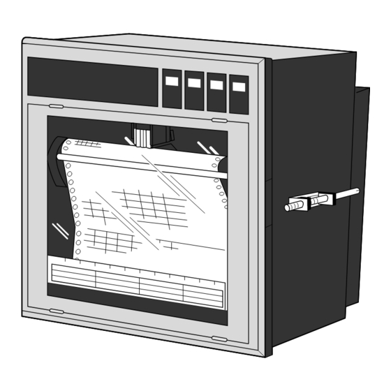
2. NAMES AND FUNCTIONS OF PARTS (2) Recording head (1) Display section (7) Key actuation section (5) Fuse (3) Lock screws (6) Power supply switch (4) Lever Display section For displays such as measurement data, units and displays of various parameters and comments display of units and data for each channel display of various parameters, comments display of units and data for each channel display of varous parameters, comments... - Page 10 Power supply switch Used to turn on and off the power. Keying operation section This is used for setting various parameters, making checks and running the equipment. FEED LIST DISPLAY RECORD SELECT ENTRY Name of key Function RECORD Operation key for starting and stopping recording. Recording starts when the key is pressed once and stops when the key is pressed again.
-
Page 11: Mounting Method
3. MOUNTING METHOD This unit is designed to be panel mounted. Mounting location Select the following location for mounting the unit. (1) A place that is not subject to vibration or impact. (2) A place where there is no corrosive gas. (3) A place that is subject to little temperature variation and is close to normal temperature (23°C) ∠... -
Page 12: Method Of Mounting Onto Panel
Method of mounting onto panel Panel Screw Screw • Tighten and fix the mounting screw attachments on the left and right. • Use a panel that is 2mm or more thick. 3 - 2... -
Page 13: Wiring
4. WIRING Before doing the wiring To carry out wiring, remove the unit's rear cover (Notes). (1) For the power cable, use a 600V vinyl-insulated cable (JIS C 3307) or a cable with equal or supe- rior performance to this. (2) Use compensating leads for thermocouple inputs. - Page 14 Wiring of input terminals (1) There are individual input terminal numbers for different channels. (2) Make connection in accordance with the relation between number of input signals by type designa- tion and channels (see section 1.3). (3) If you decide to change the type of input signals after your purchase, be sure to remember to wire up the requisite channel accordingly.
- Page 15 Resistance Thermo- bulb couple voltage Terminal number Input 7 Input 1 – – (CH7) (CH1) Input 8 Input 2 (CH8) (CH2) Input 9 Input 3 (CH9) (CH3) Input 10 Input 4 (CH10) (CH4) Input 11 Input 5 (CH11) (CH5) Input 12 Input 6 –...
- Page 16 Alarm output/remote control unit (option) About alarm outputs : (1) Alarms can be set at 4 points in each channel and alarm outputs are provided as an option for up to a maximum of 12 points. (2) When an alarm is detected, the relevant terminals are shorted. Relay contact capacity 240V/3A AC, 30V/3A DC (resistive load), 1a contact Alarm 1 Alarm 7...
- Page 17 Remote control Front panel switch Recording starts Chart speed change Data printout (across terminals (across terminals (across terminals RECORD LIST (11) to (21)) (12) to (22)) (13) to (23)) While List List Recording Recording recording printout printout starts starts is stopped starts starts Normal...
-
Page 18: Set-Up
5. SET-UP Loading chart paper Step 1 Riffle and loosen the recording paper so as to prevent overlapping feed. Step 2 Open the front flap, push the paper hold-down roller to the right and detach it. To replace chart paper while recording is in progress, carry out the above after pressing the RECORD key to stop recording. - Page 19 Step 4 With round holes (small holes) in the recording paper located on the left-hand side, set the re- cording paper so that its leading edge with both corners cut off comes to this side. Then insert the leading edge into the container with the print- ing face located upward.
- Page 20 Step 7 Press the FEED key and check that the chart paper is fed out smoothly. (Feed out about 2 folds of paper.) <If the paper is not fed out smoothly, go through the procedure from Step 2 again.> Note 1: Selection of chart paper The chart paper greatly affects the quality of the printed recording and it is also related to prob- lems such as paper jamming, etc.
-
Page 21: Recording Head Installation (Replacement)
Recording head installation (replacement) The recording head has ink and a head for recording in an integral assembly. If the ink gets used up or if it happens that there is a fault, the head can easily be replaced. As the recording head is a very delicate element, please carefully read the 'Precautions" that are noted later and handle the head with care during replacement work. - Page 22 Step 4 • If recording is in progress, stop it by pressing the RECORD key. • Raise the lever that is on the right. This re- leases the lock comma only, the recording pa- per feed section pulls forward an recording pa- per holder can be seen.
- Page 23 Step 7 Move the chart paper hold-down plate spring back up to its original position. (Check that the plate spring is not contacting the recording head.) Step 8 Return the chart paper holder to its original setting. The above completes installation of the recording head. The recording head is a consumable part.
- Page 24 Precautions in handling recording heads Note 1: If recording is halted and the recorder is not used for a long time Carry out the following in order to prevent jamming and drying-up of the ink. Remove the recording head from the main unit, make absolutely sure the cap is closed properly and store the head in a cool, dark place (average temperature 5 to 30°C).
- Page 25 Note 5: Shipping of recording head • Do not ship the unit recording head after the aluminum pack was opened up. If it is necessary to ship the unit recording head under avoidable circumstances, be sure to close the cap, and ship it as contained in a boxboard in the state where vibration and impact are eased using cushioning materials.
-
Page 26: Changing The Type Of Input Signals
Changing the type of input signals This recorder is a multi-input type which permits the input for any channel to be changed to thermo- couple, resistance bulb or DC voltage input. Follow the procedure described below if you with to change the type of input signals subsequent to purchase. - Page 27 Method of changing pin position Large PC board installed in deepth of the case. Correspondence between pin line-up and input channels 1 12 11 10 9 CH6 CH5 Changeover pins (maximum 12) Pin position for different types of inputs 4 to 20mA DC at input Pin setting is required in correspondence with types of inputs for each channel.
-
Page 28: Operation And Actions
6. OPERATION AND ACTIONS Before running the equipment: Check the following points before starting operation. Recording paper, recording head installation (1) Loading chart paper ............See Section 5.1 (2) Installation of recording head ........See Section 5.2 Wiring (1) Input terminals .............. See Section 4.2 (2) Alarm terminals (option) .......... -
Page 29: Power Switch-On And States
Power switch-on and states (1) Open the front flap. (2) The power supply switch is at the above left; switch it on. Initial switch-on of power ↓ — (A cursor appears in the upper left of the display section.) ↓ The recording head moves slowly to the left-hand end (the 0% side). -
Page 30: Test Pattern Print-Out
Test pattern print-out (1) Open the front flap, switch the power supply switch on the press the SELECT key. (2) Pressing the SELECT key several more times results in the following display. List = 1 Parameter list (3) Press the key twice;... - Page 31 Chart paper fast feed ( FEED key) • To effect fast feed regardless of recording, press the FEED key. • The speed is 3mm/s during the first second that the key is held depressed and goes to 8mm/sec after the elapse of 1 second. •...
-
Page 32: Displays And Print-Outs On Detection (Cancellation) Of Alarms
Displays and print-outs on detection (cancellation) of alarms (1) If an alarm is detected the display section gives a display as follows. Example of alarm display Example: Upper section Ch 2 measured value 123.5°C Lower section Alarm in Ch 6 Alarm Ch6 H ALM1 H alarm, relay No. -
Page 33: Over-Range, Under-Range Display And Abnormal Input Display
Over-range, under-range display and abnormal input display In all cases, for thermocouples, resistance bulbs and DC voltage input, there is a reference range for input signals. If input is outside preset range an 'Over' or 'Under' display is given. Example of over/under display °C Ch2 over over... -
Page 34: Display When Data Backup Batteries Need To Be Replaced
6.10 Display when data backup batteries need to be replaced When the voltage of back-up batteries becomes low, a display indicating that they need to be replaced is given. 'Battery End' is displayed in the display section. Example 123.5°C Battery End Replace the batteries promptly when a 'Battery End' display appears page 8-3. -
Page 35: Setting And Checking Parameters
7. SETTING AND CHECKING PARAMETERS Setting and checking (1) The parameters at the time of shipment are as indicated in the table below. Recorder operations (displays, analog trend recording) can be effected simply by switching the power on without making any adjustments, but you can set the parameters you require. (2) The record ranges are multirange and it is necessary to set the required ranges. - Page 36 Values of parameters at the time of shipment (initial values) Parameter name State at time of Remarks Method of setting shipment (initial values) checking Pass code (Cancelled) Setting range: 0 to 9999 Section 7.3 Main chart speed 25mm/h Setting range: 5 to 1500mm/h Section 7.4 Sub-chart speed 25mm/h...
-
Page 37: Outline Of Procedure For Setting Parameters
Outline of procedure for setting parameters Data display mode DISPLAY Key DISP Description of keys If pass code specifica- Pass code tion is 0, this display is • SEL : SELECT key skipped. Whatever the current state, operation moves to the next mode when this key is pressed. -
Page 38: Pass Code Setting
Pass code setting Explanation If the pass code is set to a value other than 0, it is necessary to enter the correct pass code before changing parameter setting pass code. A numerical value is specified on the screen by means of the keys and is input by the ENT key. -
Page 39: Setting The Chart Speed
Setting the chart speed (main chart speed/sub-chart speed) Explanation • Main chart speed: This is the procedure for setting the chart speed in normal operation. The setting range is 5 to 1500mm/h. (Can be set in 1mm/h steps.) • If the case of a continuous recording type, if the chart speed is too fast, the result is dashed line recording instead of continuous recording. - Page 40 Explanation Sub-chart speed: This is the chart speed when its rate is controlled by an remote control signal. The setting range is 5 to 1500mm/h. (Can be set in 1mm/h steps.) The optional external control unit is necessary. Key actuation Changing the recording paper feed of speed 100mm/h to 150mm/h by an (example) external control signal (DI)
-
Page 41: Setting Alarms
Setting alarms Explanation • Channel No.: Set the No. of the channel in which alarms are to be set. • Alarm type: The 4 types H, L, RL, RH (H, L, RL and RH can be set on the same alarm.) When No. -
Page 42: Setting The Recording Mode
Setting the recording mode The following recording modes can be set in this section. (1) Logging recording (logging) (2) Periodic print-out (3) Scale print-out (4) Auto-range recording (auto-range) (5) Enlarged/reduced recording (zoom) (6) Zone recording (zone) Setting procedure RECORD MODE LOGGING INTERVAL logging 30 min... - Page 43 Logging recording (logging) • In this case, there is no analog trend recording but a record of data (the time channel Nos., measured values, units) is produced at specified intervals of time (10 to 60 minutes can be specified.) • If there is detection or clearing of an alarm during logging print-out, this is printed on the right-hand side of the recording paper.
- Page 44 Auto-range recording (auto-range) If input outside the record range occurs, recording is effected with the record range automatically changed. The record range after a change goes 50% of the span to the plus side or the minus side. Note that the recording span does not change.
- Page 45 Note 2: If zoom recording is specified, scale print-out digits are printed only for the 4 points 0% and 100% of the record range, and the boundary value 1 and the boundary value 2. (Boundary value scale digits are printed only if the record position is 15 to 85% and when the difference between boundary value 1 and boundary value 2 is less than 7%, only the small chart position is printed.) Example: With a record range 0 to 500°C, the boundary value 1 of 200°C, chart position of 30%, and the boundary value 2 of 300°C, chart position of 70%.
-
Page 46: Setting Record Ranges
Setting record ranges Explanation An individual record range is set for each channel. 'Record range' means the 0% and 100% position scale on recording paper. If DC voltage input scaling is set and used, set the record range after setting scaling. -
Page 47: Setting Kind Of Input, Skip, Unit, Filter, Scaling, Subtraction
Setting kind of input, skip, unit, filter, scaling, subtraction Explanation The type of input (B, R, S, K, E, J, T, N, W, L, U, PN thermocouples, JPt, Pt, voltage, COM, copy skip), units (°C, °F, mV, V), filters (time constant) and in the case of DC voltage input, the scaling, input range, engineering value (scaling value), units, rooters (square root extractors) and logarithmic arithmetic operation are specified for each channel. - Page 48 Setting and changing input signal type Thermocouple Resistance bulb DC voltage To effect the changes refer to Section 5.3 to change the positions of the setting pins. Then, use the following parameter specification to specify the correct input signal type. Example: Changing 5V input signal type of channel 6 to thermocouple input Use the keys to select channel 6 and press the ENT key.
- Page 49 • The decimal point positioning When the ENT key is pressed following setting of the upper limit value, the lower limit value and the upper limit value both flash. The positions of the decimal points can now be changed by pressing the keys.
- Page 50 Logarithmic calculation • Set the logarithmic calculation function of each channel. ON: Valid OFF: Invalid • Contents of logarithmic calculation function (1) Indication and print format: 9.9E±9 Indication part: -9 to 9 Fixed-point part: First decimal place –9 Data range: 1.0 x 10 to 1.0 x 10 (When simultaneous display of 6 channels is made by the display unit on the front face, display is –9...
- Page 51 Precautions at the time of setup/change to input signal type, scaling and/or differential arithmetic operation If you change the specification for input type, scaling, and subtract calculation, corresponding parameters will be initialized as follows. Make sure to check and re-configure the paramters. Timing Change input type set OFF to scaling Set ON to scaling...
- Page 52 Table of unit codes Code B Classification Code A °C °F Temperature, humidity Vol% Flow rate t/day kg/day g/day /day /day N1/day 1/day cc/day kg/h N1/h cc/h t/min kg/min g/min /min /min N1/min 1/min cc/min t/sec. kg/sec. g/sec. /sec. /sec N1/sec.
-
Page 53: Setting Tag Nos
Setting Tag Nos. Explanation A Tag No. for each channel is specified by up to 8 alphanumeric characters. Specified Nos. are printed on the recording paper, so as to identify the channel to which measure- ment record applies. Key actuation To change TAG No. -
Page 54: Message Print Specification
7.10 Message print specification Explanation • Message print is possible at the occurrence of any events. • Up to 10 messages, each containing a maximum of 16 characters, can be registered by the user. • Messages can be specified in numerals, alphabets and other special symbols. Print colors (orange, red, blue, green, purple, black) and print positions (0 to 150mm) can also be specified. - Page 55 Print position specification 1) Message print position can be selected by the keys. Press the ENT key after selection. 2) The print range is 0 to 150mm. The size of each print character is 2mm. Example: Print position for chart Print position Print position Print position...
- Page 56 (g) ALM1 1 OFF • When "alarm" is selected, message is printed at the time of ON or OFF of alarm of the specified channel. Example: Message are print at ON of alarm of CH2. Press the keys for CH2, then press the ENT key. Next Print position=0mm press the keys for LL alarm, then press the ENT key.
-
Page 57: List Print-Out Specification
7.11 List print-out specification Explanation • This is used for any of the parameter list print-outs, scale print-outs, test pattern print-outs, daily report lists, totalize lists and message print. • The data display mode during printing of a list is the normal measurement display mode. •... -
Page 58: Daily Report Specification
7.12 Daily report specification Explanation • Instantaneous value data for each hour in each channel over a 24-hour period (max. 24 data items) and the average values, maximum values and minimum values of these lots of data items are printed out. (Printing time: about 24 minutes/6 channels for 24-hour setting) (Analog trend recording cannot be performed during print-out.) •... - Page 59 Note: Relations between operation start times and print-out times When setup of daily report start time and end is changed, the print list immediately after the change is not compensated. After the time setup was changed, turn off the daily report or integration (buffer clear) is possible.
-
Page 60: Specifying Totalize Function
7.13 Specifying totalize function Explanation • A maximum 24-hour lots of wholly totalizing value data in each channel (max. 24 data items) and the value of the sum totals of these lots of data items are printed out (Printing time: about 24 minutes/12 channels at 24 hour setting). -
Page 61: Transmission Specification (Option)
7.14 Transmission specification (option) Explanation The transmission function (option) of this unit serves for transmission of measured values and recep- tion of specified condition, etc. through an RS-485 interface or T-link. For details, please see the separate booklet the 'RS-485 interface Manual' or T-link interface Manaul'. Items for specification in this unit are as follows. - Page 62 The items which can be accessed by transfer are as follows. Item READ WRITE Operation Recording start/stop Momentary value list print Recording paper fast feed (FEED) Display Measured value Time Alarm Recording paper end (chart end) Carriage error Battery end Burn-out Over/under-range Manual print...
-
Page 63: Setting The Time
7.15 Setting the time Explanation Year, Month, Day, Hours, Minutes are displayed in that order going from the left. The initial setting value is set to JST. Key actuation Clock is 1 minute slow, (Correction of 35 minutes to 36 minutes) (example) Key operation Explanation... -
Page 64: Clearing The Ink Monitor
7.16 Clearing the ink monitor Explanation This is a function or warning and detection of ink dry-up. Normally, this operation is not required but always set to "Clear" when you replace the recording head with a new one. If you forget to make the setting "Clear", operation continues from the previous count value, and so the ink dry-up warning-detection count is actuated and there is a con- stant ink dry-up warning-detection print-out. -
Page 65: Turning The Chart Illumination Lamp On/Off (Option)
7.17 Turning the chart illumination lamp on/off (option) Explanation If the unit is provided with recording paper illumination (option), the lamp can be turned on and off by keyboard operation. Key actuation Bolder turning chart illumination light off (example) Key operation Explanation Display Press the SEL key several times to display... -
Page 66: Maintenance - Inspection
8. MAINTENANCE - INSPECTION Carry out periodic maintenance and inspection to keep the equipment in good condition. Pay particular attention to the items noted below and make replacement with spares when necessary. Inspection, Procedure Maintenance Items Recording head The recording head is a consumable part. replacement If there is no more ink, replace the head with a new one. - Page 67 Replacing the battery • If a "Battery end" display appears in the display section replace the batteries. [Note that turning the power off while a 'Battery end' display is on may result in erasure of specified data.] • Proceed with the power switched on. Open the front flap and follow the procedure described below to replace the batteries.
- Page 68 Step 4 Use a plastic screwdriver to mount a new battery – unit. When doing this be careful to get the bat- tery polarity right.Upper: – Lower: + Battery part No.: TK7G8473P1 Step 5 • After completing the battery replacement, return the main unit to its original state. •...
- Page 69 Flourescent lamp replacement When the lamp remains OFF, dark or blinks, it needs to be replaced. • Turn OFF the power. • Open the front door and replace the lamp using the following procedures. Step 1 Loosen (anticlockwise) the lock screws on the left and right and remove them.
- Page 70 Step 4 Remove the connectors (2 places) connecting the display unit to the main unit. Connector Connector Step 5 Loosen the mounting brackets on both sides of the fluorescent lamp at the rear of the display unit. Remove the brackets from the display unit. Screw Lamp mounting bracket...
-
Page 71: Application Functions
9. APPLICATION FUNCTIONS This section gives some explanations and information about following functions. (1) Print/recording adjustment (2) Zero/span adjustment for analog trend recording position (3) Alarm latch and totalize print-out settings (4) Shift of measured values (5) Preparation of unit (6) External output of recording error Any of the above adjustments are done with software so operation is quite simple. -
Page 72: Zero/Span Adjustment For Analog Trend Recording Position
Zero/span adjustment for analog trend recording position Explanation The zero print (0% point) and span point (100% point) for analog trend records on the recording paper are adjusted. There is no need to connect a calibration instrument for this adjustment. Operation (1) Press the REC key to stop recording operation. -
Page 73: Setting Of Alarm Latch And Integrated Value Print-Out
Setting of alarm latch and integrated value print-out (1) Setup of alarm latch Explanation • Alarm display output is retained even if alarm is OFF. • Latch OFF and alarm OFF are printed at OFF of alarm latch function or at input of DI3 (terminal 13 to 33). -
Page 74: Setting Of Pv Shift
Setting of PV shift (1) PV shift function • It is possible to arithmetically operate the measured value and to record the display the result. • Set the inclination and shift value for PV shift arithmetic operation. The conversion graphs after execution of shift arithmetic operation and inclination arithmetic opera- tion are indicated below. -
Page 75: User Definable Unit
User definable unit Explanation The unit may be created using numerals, alphabetic letters, etc. Up to 7 digits can be set, and units of 12 types can be registered. Operation Example: To create unit kgf/cm for code A = 2, B = 10. (1) Have parameter "Ink alarm clear"... -
Page 76: Setting Of Record Error External Output
Setting of record error external output Explanation • Relay output to the exterior is made on occurrence of chart end, battery end, carriage error or ink end. • Relay output to the exterior also occurs when an alarm occurs and when a recording error occurs, if output setup is made for the relay, which is the same as the relay No. -
Page 77: Calibration Of Measured Value
Calibration of measured value Explanation Normally, no adjustments are required, except when measured value displayed is excess of the guaran- teed value. With calibration input signal applied, adjustment is made automatically with software. Apply a correct calibration input to the object channel. Note: Use of incorrect calibration input signal will results in wrong operation. -
Page 78: Change Of Record Color
9.8 Change of record color Explanation • The recording and print color of each channel is changed. Operation (1) Have the calibration screen displayed by the operation described in section 9.7. The recording color change screen appears when the SEL ADJUST Ch key is pressed. -
Page 79: Troubleshooting
10. TROUBLESHOOTING If the unit does not function properly, check what is wrong and refer to the following table to see what action to take. For complicated trouble, consult with our service engineer. State Points to check Action to take Does not move at all (1) Is the power supply terminal connection Connect correctly... - Page 80 State Points to check Action to take Ink does not come out Carefully note the points described on page 5-7 Refer to "Note 6: If the ink is not even though there is no in relation to the recording head (i.e., the notes sprayed"...
-
Page 81: Examples Of Records And Print-Outs
11. EXAMPLES OF RECORDS AND PRINT-OUTS Note: In the case where the chart speed is 301 mm/h or more (continuous recording type) or 51 mm/h or more (chopper bar recording type), there are no periodic print-outs, scale print-outs (but print-out can be made manually;... -
Page 82: Digital Print-Out (Instantaneous Values)
Example of 12 continuous records 11.2 Digital print-out (instantaneous values) Pressing the LIST key effects immediate print-out of current values. (See Section 6.4 (2)) Year, month, day, time Engineering units Measured value Channel No. Note: "—" (hyphens) are printed for a channel for which skip has been set. Furthermore, no engineering unit is printed. -
Page 83: Parameter List Print-Out
11.3 Parameter list print-out The specified contents of parameters are all printed out together on the recording paper. (See Section 7.10) 11.4 Test pattern Yellow Orange Blue Green Purple Black 11.5 Scale print-outs The scales of specified channels are printed. (See Section 7.11) Scale digits Channel 6 Channel 5... -
Page 84: Daily Report Print-Out
11.6 Daily report print-out This consists of print-out of the data for a max. 24-hour period (max. 24 data items in hourly units) for specified channels. The maximum, minimum and average values of the instantaneous values on the every full hour from the daily report start time to the daily report end time are printed out. -
Page 85: Data Sum List Print-Out
11.7 Data sum list print-out This consists of print-out of the data for a max. 24-hour period (max. 24 data items in hourly units) for specified channels. The integrated values for each hour and the totals of the integrated values from the integration start time to end time are printed out (See Section 7.13 for the specification procedure.) Channel No. -
Page 86: Logging
11.9 Logging The instantaneous value of the various channels are printed out at set intervals of time. (See Section 7.6 (1).) Data, time Channel No. Engineering units Measured value 11.10 Alarm print-outs When an alarm is detected and cancelled, the time of detection and cancellation, the channel No., the type of alarm and the relay No. -
Page 87: Record Start Mark
11.13 Record start mark When recording starts, a record start mark is printed at the left-hand edge of the recording paper (outside the 0% scale line). Recording start mark 11.14 Chart speed change mark If a change in the speed of the recording paper is ordered, a chart speed change mark is printed at the left- hand edge of the recording paper (inside the 0% scale line). -
Page 88: Specification
12. SPECIFICATION Input Section • Number of input points: 7 classes: 1, 2, 3, 6 or 12 continuous records and 6 or 12 dot record • Input signals: Thermocouple input ....B, R, S, K, E, J, T, N, W, L, U, PN Resistance bulb input .... - Page 89 • Accuracy, resolution: Performance at standard conditions (23±2°C, 55±10% RH, power supply volt- age and frequency fluctuation within ±1%, warm-up time 30 minutes or more, vertical mounting, environment with no adverse effects of external noise, etc.) Indication (digital dis play) Record Type of input Accuracy...
- Page 90 Display section • Display system: Fluorescent display (blue-green), 20 characters x 2 lines • Display characters: 5x7 dots, character height 5.0mm, width 3.5mm • Display contents: (1) Measured values: Temperature ... to 1st decimal place Voltage ... 6 places (including symbols decimal point) (2) Channel Nos.: 2 characters (1 to 12) (3) Engineering units: Maximum 7 places (°C, °F, %, kg/cm , mmH...
- Page 91 Construction • Mounting method: Mounted in panel (vertical panel) Tilt angle α = 90 to 60° ∠ α • Material: Case: steel plate Front flap frame: glass-containing polycarbonate • Mass: Approximately 6kg (without options) Approximately 7kg (with all options) • External dimensions: 288 x 288 x 199mm •...
- Page 92 • Effect of input source resistance and wiring resistance: Thermocouples: 10µV per 100Ω Variation with resistance value equivalent to 0.1% of the input value in the case of voltage Indication variation ..±(0.1% of reference range + 1 digit) Recording variation ..±0.2% of record span Variation with fluctuation of 10Ω...
- Page 93 • EMC Standards: EN50081-1 (1992), EN50082-1 (1992) • Dust/drip-proofing: IP50 Supplementary specification 1. Recording paper illumination: Cold cathode fluorescent lamp 2. Alarm output external control: Special-purpose unit needed. Unit can be mounted in rear of in- strument as extra equipment at a later date. (1) Alarm output (DO): 6 or 12 point of relay contact output (1a), can be for individual chan- nels or perform OR operation.
- Page 94 Optioanl accessories (available separately) Article name Type Specification Shunt resistance SRZT8101 10Ω±0.1%, for 4 to 20mA DC, 10 to 50mA DC input Standard functions Function Content Arbitrary range setting Any record range can be set for each individual channel Arbitrary specification Any type of input can be specified for each individual channel of input signals Skip function...
- Page 95 Function Content Recording color change To change the recording and print color of each channel. function Daily report function Max. 1-day lots (lots of max. 24 data items) of the instantaneous values at each full hour for each channel each day are stored and printed out. At the same time, maximum values, minimum values and average values are printed out too.
- Page 96 Temperature and Humidity Control Specialists Head Office: 2-30-10 Kitamachi, Nerima-Ku, Tokyo 179-0081 Japan Phone: +81-3-3931-7891 Fax: +81-3-3931-3089 E-MAIL: exp-dept@shimaden.co.jp URL: http://www.shimaden.co.jp...
Need help?
Do you have a question about the SR186A Series and is the answer not in the manual?
Questions and answers