Table of Contents
Advertisement
Quick Links
Please ensure that this instruction manual is given to the final user of the instrument.
Preface
Thank you for purchasing Shimaden products. Please check that the delivered product is the correct item that you ordered. This instruction manual is meant for
those who will be involved in the wiring, installation, operation and routine maintenance of the SD17 series, and describes about cautions, mounting, wiring,
functions, and operation. Please observe the contents, and always keep the manual close at hand when handling this instrument.
The following headings give a description of matters requiring user attention concerning safety, damage to machines and equipment, additional explanations and
commentaries are described under the following headings.
Items concerning matters that may lead to an accident producing human injury or death, if the warning is not observed.
WARNING
CAUTION
Items concerning matters that may lead to an accident producing damage to machines or equipment, if the caution is neglected.
Note
Additional explanations and commentaries.
Note
Safety cautions
WARNING
•
The SD17 Series digital indicator are designed for industrial use to control temperature, humidity and other physical values. Do not apply this instrument to
other objects in a way that may cause grave effects on human safety.
•
In using this product, be certain to house it, for example, in a control panel, so that the terminals cannot come into contact with personnel.
•
Do not take this instrument out of its case or put your hand or any conductor inside the case. Such conduct may lead to an accident that endangers life or
causes serious injury due to electric shock.
CAUTION
•
To avoid damage to the connected equipment, facilities or the product itself due to a fault of the product, safety countermeasure must be taken before usage,
such as proper installation of the fuse and the overheating protection device.
•
An alert symbol
is printed on the terminal nameplate attached to the case. It warns not to touch the electrical charging parts when the power is being
supplied, so as to avoid the risk of electrical shock.
•
Install a switch or breaker on the external source power circuit connecting to the source power terminal as a means to shut down the power.
The switch or breaker should be installed adjacent to the instrument in a position that allows the operator easy access.
•
Regarding the fuse:
Since this instrument has no built-in fuse, make sure to install a fuse in the electric circuit connecting to the source power terminal.
Install the fuse in a position between the switch or breaker, and the instrument and attach it to the L side of the source power terminal.
Fuse Rating: 250V AC 1.0A/Time-lag (T) or Medium Time-lag (M)
•
The load of voltage and current to be applied to the output terminal (analog output) and the alarm terminal must be within the rated range. If the range is
exceeded, the instrument will overheat causing the risk of the instrument being damaged and its life reduced.
As for the rating, please refer to "11. Specification."
The unit connected to the output terminal should conform to the requirements of IEC61010-1.
•
Do not apply over-rated voltage or current to the input terminal. That will cause the risk of the instrument being damaged and its life reduced.
As for the rating, please refer to "11. Specification."
In case the input type is voltage (mV or V) or current (4 - 20mA), the unit connected to the output terminal should conform to the requirements of
IEC61010-1.
•
Take care to prevent metal or other foreign matter from obstructing the ventilating hole for heat radiation. It will cause damage to the instrument and may
even result in fire.
•
Do not block the ventilating hole. Also avoid dust accumulation. Any rise in temperature or insulation failure may result in a risk of the instrument being
damaged and its life reduced. As for the clearance space for installing the instrument, refer to "2-3 External dimensions and panel cutout."
•
Repeating withstanding tests on voltage, noise, surging may lead to the deterioration of the instrument, so please be careful.
•
Strictly refrain from remodeling and using the instrument improperly.
•
It takes 30 minutes to display the correct temperature after applying power to the digital Indicator. (Therefore, turn the power on more than 30 minutes prior
to the operation.)
•
To ensure safety and maintain the functions of this device, do not disassemble this device. If this device must be disassembled for replacement or repair,
contact your dealer.
•
This device is designed for mounting on the panel. Only the device mounted on the front of the panel facing outward is of protection class of IP66. Do not
use for the device not facing outward or in environment where water or solids in excess of IEC60529 may get inside.
Copyright © SHIMADEN CO., LTD. All rights reserved.
Digital Indicator
SD17 Series
Instruction Manual
Detailed Version
1
MSD17-E01-B
Jun. 2022
Advertisement
Table of Contents

Related Manuals for Shimaden SD17 Series


Summary of Contents for Shimaden SD17 Series
- Page 1 Preface Thank you for purchasing Shimaden products. Please check that the delivered product is the correct item that you ordered. This instruction manual is meant for those who will be involved in the wiring, installation, operation and routine maintenance of the SD17 series, and describes about cautions, mounting, wiring, functions, and operation.
-
Page 2: Table Of Contents
10-2. Connecting with host computer ········································································································· 12 (1) RS-232C ····························································································································································· 12 (2) RS-485 ······························································································································································· 12 (3) Control of 3-state output ········································································································································· 12 10-3. Shimaden protocol ·························································································································· 13 (1) Communication overview ········································································································································ 13 (2) Recommended communication format ······················································································································ 13 (3) Overview of protocol format ···································································································································· 13 (4) Basic format section ··············································································································································... -
Page 3: Introduction
Termination Resistor (When selecting Communication option RS-485) 1 pc. Note Contact our local agent or exp-dept@shimaden.co.jp via e-mail for any problems about the product, accessories or related items. 1-2. Notes for use • Avoid operating the front panel keys with hard or sharp objects. Lightly touch the operating keys with your fingertips for operation. -
Page 4: External Dimensions And Panel Cutout
SD17 Instruction Manual 2-3. External dimensions and panel cutout External dimensions Panel cutout Unit: mm Unit: mm 2-4. Wiring WARNING • When wiring the unit, be sure to cut the power supply OFF, or there will be a risk of electric shock. •... -
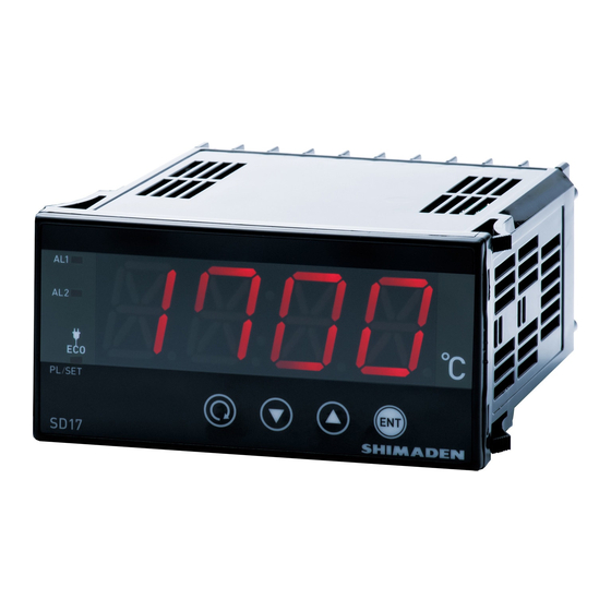
Page 5: Names And Functions For Front Panel
SD17 Instruction Manual 3. Names and functions for front panel 3-1. Names Front panel [1] Monitoring LEDs [2] LED display [3] Key switches for measured value 3-2. Functions [1] Monitoring LEDs [3] Key switches • AL1 (Alarm 1) output monitoring LED (red) Parameter key The LED lights when the assigned alarm is ON. -
Page 6: Instruction For Each Screen
SD17 Instruction Manual 6. Instruction for each screen 6-1. Screen sequences Each screen is classified by the screen frame as follows. Screens displayed or not displayed Screens displayed when any option is added. Screens always displayed. depending on some conditions. Mode 1 Screen Group Mode 0 Screen Group initial screen... -
Page 7: Power On Screen Group
SD17 Instruction Manual 6-2. Power ON Screen Group 0-2 Alarm 2 latching release This screen is displayed when Alarm 2 is in the The following information is displayed automatically. REt2 latching state, and is used for releasing it from that Model name state. -
Page 8: Mode 1 Screen Group
SD17 Instruction Manual 6-4. Mode 1 Screen Group 1-7 Input scaling lower-limit value The scaling lower-limit value for voltage/current in_L Mode 1 Screen Group consists of screens that are used less often that Mode input is displayed or can be set. 0 screens, and are required according to the input type or controllability. - Page 9 Processing the Write command, in SHIM : Shimaden protocol particular, may take about 400 msecs in some case. : MODBUS ASCII : MODBUS RTU...
-
Page 10: Alarm Output
SD17 Instruction Manual 1-26 Display color 1-28 Alarm action: display blinking The color of display can switch red and white. The display can blink by alarm action. dcol Ebri RED : red OFF : display not blinking WHIT : white ON : display blinking RED, WHIT... -
Page 11: Communication
Number of connectable devices 31 devices max. (for RS-485) Delay 1 - 100 msec Communication protocol Shimaden protocol, MODBUS ASCII, MODBUS RTU Communication mode type COM1 or COM2 Data format 7E1, 7E2, 7N1, 7N2, 8E1, 8E2, 8N1, 8N2 Control code... -
Page 12: Connecting With Host Computer
SD17 Instruction Manual 10-2. Connecting with host computer (1) RS-232C This indicator is provided with only 3 lines for input and output, i.e., for data transmission, data reception and grounding for signals, not with any other signal lines. Since the indicator has no control line, control signals should be handled on the host side. The following drawing shows an example of control signal processing methods. -
Page 13: Shimaden Protocol
(3) Overview of protocol format Shimaden protocol is composed of "Basic format section I", "Text section", and "Basic format section II." The protocol format send from host and the one respond from slave are common. Note that the format of Text section and BCC operation result is different. -
Page 14: Text Section
SD17 Instruction Manual 3. Exclusive OR operation XOR operation from after the start character ( ) to text end character ( ) in unit of byte (one ASCII character). Ex.: ADDR ASCII convers ion 3AH = 60H ^ indicates exclusive OR In this example, the ASCII converted string from 6 or 0, the lower 1 byte value of 60H which is the result from XOR, will be stored in the higher/the lower field of BCC respectively. -
Page 15: Read Command
SD17 Instruction Manual (6) Read command The Read command 'R' is used by a master to read (take) various data in slave. Command data format (from master) □ ‘R' (52H) indicates that this is the Read command. □ FIRS T ADDRESS The start data address of data to be read. -
Page 16: Response Codes
SD17 Instruction Manual (8) Response codes The following lists response codes of Shimaden protocol. Other than 00H (30H 30H) are error codes. Response code Condition Descriptions 00H(30H 30H) Communication ends successfully The response code to a command indicating that the communication ends normally. -
Page 17: Commands Of Modbus Ascii Mode
SD17 Instruction Manual MODBUS RTU mode The following is a message format of MODBUS RTU mode. DATA BLANK ADDR FUNC BLANK Communication address of slave (destination address) Set the communication address. For example, if the address is "100 (64H)", the valid value is "64H." The communication address setting range is 1 to 255 for this instrument. - Page 18 SD17 Instruction Manual Write command The Write command is used by a master to write (input) various data to a slave. It's necessary to change the communication mode to LOC-> COM at the time of light command use. But, it isn't possible to change this communication mode by a front key.
-
Page 19: Commands Of Modbus Rtu Mode
SD17 Instruction Manual (4) Commands of MODBUS RTU mode Under MODBUS RTU mode, the Read command, the Write command and the Loop back command are offered. Read command The following is a description about the Read command. The Read command is used by a master to read (take) various data in slave. Command data format (from master) Function code 03H indicating that this is the Read command. -
Page 20: Function Codes
SD17 Instruction Manual (5) Function codes A function code indicates the command type for a slave. The same function code of the master is returned from a slave in case that the process terminates successfully. If the process is abnormally terminated, the MSB (Most Significant Bit) to the original function code is set to 1, and this revised function code is returned. -
Page 21: Ascii Code Table
8000H is returned. In case of Shimaden protocol or MODBUS ASCII mode, 7FFFH is converted into 37H 46H 46H 46H, and 8000H is converted into 38H 30H 30H 30H. In case of MODBUS RTU mode, 7FFFH is converted into 7FH FFH, and 8000H is converted into 80H 00H. -
Page 22: Specification
SD17 Instruction Manual 11. Specification Display Digital display Process value (PV), 11-segment, 4-digit red LED (approx..20mm character height) (Optional) 11-segment,4-digit white LED(approx..20mm character height) Action indication PL/SET (green): lit when parameter value is displayed ECO (green) : lit when screen-saver mode is set AL1/AL2 (red) : lit when alarm signal is output Display accuracy ±... - Page 23 31 devices max. (for RS-485) devices Delay 1 - 100 msec Communication protocol Shimaden standard protocol, MODBUS ASCII, MODBUS RTU (start character and BCC operation method can be selected for Shimaden standard protocol). Communication mode COM1 or COM2 type Isolation Isolated between communication and input, between communication and alarm output, between communication and analog output (sensor power supply), or between communication and system.
- Page 24 1.0 - 4.0 mm Panel cutout H45 x W92 mm Weight Approx. 250g The contents of this manual are subject to change without notice. https://www.shimaden.co.jp Any questions should be directed to your local agent, or send an e-mail to exp-dept@shimaden.co.jp. Printed in Japan...
Need help?
Do you have a question about the SD17 Series and is the answer not in the manual?
Questions and answers