
Subscribe to Our Youtube Channel
Summary of Contents for Rich electric INVERTEK SUNSTAR MPPT Series
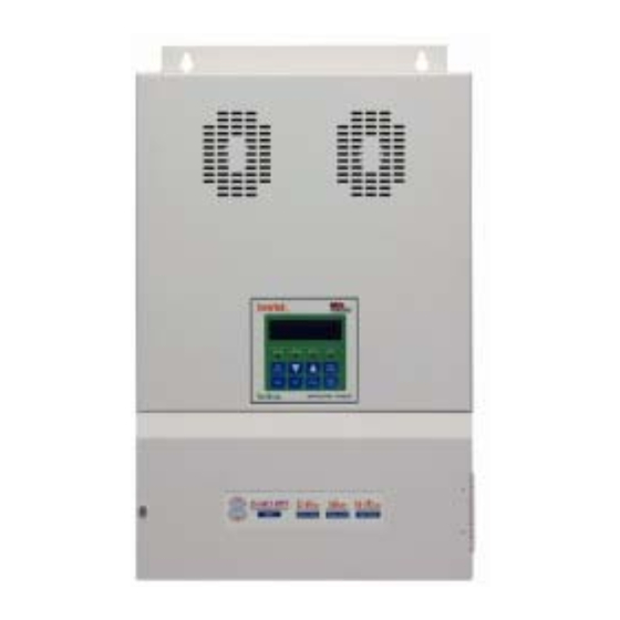
- Page 1 利 佳 興 業 股 份 有 限 公 司 RICH ELECTRIC CO.,LTD. INVERTEK ® SUNSTAR MPPT SERIES SOLAR CHARGE CONTROLLER SS-50C / SS-80C / SS-80CX / SS-160CX MPPT Installation and Operation Manual MANUAL VER.1, 0809...
-
Page 2: Table Of Contents
CONTENTS Introduction ..........................Ⅳ Feature ............................IV Specification..........................VI Dimension ...........................VII Chapter 1 Installation........................ 1-1 1.1 Loads Requirement..................1-1 1.2 Battery Voltage System ................... 1-1 1.3 PV Array Voltage..................... 1-1 1.4 Maximum Voc ....................1-1 1.5 Shunt (BCS)...................... 1-2 1.6 Battery Temperature Sensor (BTS-3)............1-2 1.7 Battery Voltage Sensing (BVS) ............... - Page 3 G Group: Data Log....................4-5 Chapter 5 Programming Constants ..................5-1 U Group: Operation ....................5-1 A Group: Initialize....................5-4 B Group: Battery Setup................... 5-5 C Group: MPPT Setup.................... 5-8 D Group: Auxiliary Relay 1 ..................5-9 E Group: Auxiliary Relay 2 .................. 5-12 F Group: Parallel Setup ..................
-
Page 4: Introduction
Introduction The SunStar MPPT is a highly reliable solar battery charger and its most critical feature is to maximize the harvest energy from the PV array into the battery by using the advanced technology of Maximum Power Point Tracking (MPPT). The battery types that the SunStar MPPT charge include Flooded Lead Acid (FLA), GEL ,AGM chemistries and LiFePo in the range of 12Vdc, 24Vdc, 36Vdc and 48Vdc nominal. - Page 5 batteries; 2/3/4-stage charging with adjustable set points for all parameters. Wire the PV modules in series up to 112VDC normal (140VDC Max) for SS-50C Series, SS-80C Series and 192VDC normal (240VDC Max) for SS-80CX Series, SS-160CX Series. Easy stacking of up to 16 units in parallel for high currents. Precision charging of 12V/ 24V/36V/48V batteries with easy set-up and using battery voltage sense (BVS) wires.
-
Page 6: Specification
Specification Model No. SS-50C MPPT SS-80C MPPT SS-80CX MPPT SS-160CX MPPT Maximum output current (Continuous at up 50℃ 50 Amps 80 Amps 80 Amps 160 Amps ambient temperature) Battery Voltages 12,24,36,48 VDC Normal Max PV Input Current 40 Amps 70 Amps 70 Amps 140 Amps 16~112VDC Operating... - Page 7 Dimension for SS-50C MPPT Unit: mm Fig-1...
- Page 8 Dimension for SS-80C MPPT Dimension for SS-80CX MPPT Unit: mm Fig-2 VIII...
- Page 9 Dimension for SS-160CX MPPT Unit: mm Fig-3...
-
Page 10: Chapter 1 Installation
Chapter 1 Installation 1.1 Loads Requirement The SunStar MPPT series plays a major role in planning your PV system. The first step in planning an efficient PV system is to calculate the load requirement. In order to calculate the anticipated load requirement, it is important to determine average and peak load consumption. -
Page 11: Shunt (Bcs)
1.5 Shunt (BCS) The Shunt is an optional component and it is required for the SunStar MPPT to achieve to the optimal operation levels and it functions as a hub for connecting measurement sensors. The main purpose of the shunt is to allow the SunStar MPPT to measure current drawing into and out of the battery. - Page 12 Fig-4...
-
Page 13: Installation Steps
1.9 Installation Steps Example: SS-80C MPPT Before starting the SS-80C, keep the breakers, controllers in OFF position. 1. Locate the battery and SunStar MPPT Series and make sure the safety distance is at least 1 meter long. 2. Install a 100 Amp rated DC breaker and connect it to the Battery + . 3. -
Page 14: Chapter 2 Wiring
Chapter 2 Wiring 2.1 Front Panel Display LCD Meter Indicator PB 3 PB 2 PB 1 PB 4 PB 8 PB 7 PB 6 PB 5 8 Push Buttons Push buttons Name Description Data write-in key UP key to increment setting values. UP key to go to the next selection or constant. - Page 15 Reset key to reset the fault. ESC key to return to the last selection level. Quick function key to the Main Menu: Data Log Quick function key to the Main Menu: Programming Quick function key to the Main Menu: Initialize Quick function key to the Main Menu: Operation 4 LED Indicators Flashing/...
-
Page 16: Control Terminal Connection
2.2 Control Terminal Connection A B C D E F J K L M N O Fig-4 Connections Details A BVS- Connecting terminal to Battery Voltage feedback Negative B BTS- Connecting terminal for Battery Temperature Sensor Negative C BVS- Connecting terminal for optional Shunt Negative D BVS+ Connecting terminal to Battery Voltage feedback Positive E BTS+... - Page 17 J MA1 Connecting terminal for the contact A of auxiliary 1 K MC1 Connecting terminal for the common contact of auxiliary 1 L MB1 Connecting terminal for the contact B of auxiliary 1 M MA2 Connecting terminal for the contact A of auxiliary 2 N MC2 Connecting terminal for the common contact of auxiliary 2 O MB2...
-
Page 18: Parallel Connection
2.3 Parallel Connection The parallel connection of SunStar MPPT series can be up to 16 units (1 Master and 15 Slaves) and in the parallel system, there is only one Shunt which needs to be connected to the Master unit to measure the total accumulated current. F-01=Master F-01=Slave F-01=Slave... -
Page 19: Structure Of User Constants
Chapter 3 User Constants 3.1 The following is the structure of user constants. U-12 Battery SOC U-13 Battery Current U-14 Battery Amp Hours U-15 Battery Temperature U-16 Parallel COMM Status U-17 Serial Number Initialize A-01 Access Level A-02 Init Parameters A-03 Password 1 A-04 Password 2 Programming... -
Page 20: Initialization Stage Flow Chart
3. 2 The following is the “Initialization Stage Flow Chart”. - Page 21 SAVE: If SAVE is selected by pressing key, the controller will save the entered settings and operate with them RCLL (RECALL): Pressing key will return to the last setting prior to entering setup. DFLT (DEFAULT): If DFLT is selected by pressing key, the controller will revert to and operate at default settings based on the original voltage, battery type and capacity entered in the initialization process.
-
Page 22: Operation Stage Flow Chart
3.3 The following is the “Operation Stage Flow Chart”. Main Menu Main Menu-Operation Menu Constants... - Page 23 Main Menu-Initialize Menu Constants Constants Edit Data Enter Main Menu-Programming Group B Menu Group Constants Constants Edit Data Enter...
- Page 24 Main Menu-Programming Group C Menu Group Constants Constants Edit Data Enter Main Menu-Programming Group D, D-01= ON or OFF Menu Group Constants Constants Edit Data Enter...
- Page 25 Main Menu-Programming Group D, Auxiliary 1 ON/OFF Condition Setting Menu Group Constants Constants Edit Data Enter *** Main Menu *** Operation ▲ *** Main Menu *** Initialize ▲ DATA ENTER Group B *** Main Menu *** Battery Setup Programming ▼ ▲...
- Page 26 Main Menu-Programming Group E, Auxiliary 2 ON/OFF Condition Setting Menu Group Constants Constants Edit Data Enter...
- Page 27 Main Menu-Programming Group F Menu Group Constants Constants Edit Data Enter...
- Page 28 Main Menu-Programming Group O Menu Group Constants Constants Edit Data Enter 3-10...
- Page 29 Main Menu-Data Log Menu Constants Constants Edit Data Enter 3-11...
-
Page 30: Chapter 4 Constants List
Chapter 4 Constant List Factory Main Menu Group Constant LCD Display Range Unit Remark Page Setting =xxx.xV xxx.xAmps 0.1V ─ ─ U-00 =xxx.xV xxx.xAmps 0.1A ─ ─ U-01 Input Voltage 0.1V ─ ─ U-02 Input Current 0.1A ─ ─ U-03 Output Voltage 0.1V ─... - Page 31 Factory Main Menu Group Constant LCD Display Range Unit Remark Page Setting ─ B-05 BAT. MAX Charge Amps 0~80/0~160 NOTE 6 FLOOD- 13.9~15.2 0.1V 14.6 Set Absorption B-06 Volts 13.7~15.1 0.1V 14.1 13.6~15.1 0.1V 14.1 0~ 99 Hr B-07 Set Absorption Time 1 Min 2 Hr 59 Min...
-
Page 32: D Group: Auxiliary Relay 1
Factory Main Menu Group Constant LCD Display Range Unit Remark Page Setting Auxiliary Relay 1 OFF, ON, Solar Voltage, Output Volts, Battery Volts, OUT Current, ─ D-01 Set Aux Relay 1 Mode BATT Current, SunStar Temp. Battery Temp. SunStar Time Battery SOC, Output Volts Aux RY1 ON Condition... -
Page 33: E Group: Auxiliary Relay 2
Factory Main Menu Group Constant LCD Display Range Unit Remark Page Setting 00~23 Hr When D-01=SunStar Time 1 Min 5-11 00~59 Min D-03 When D-01=Battery SOC 0~100 5-11 0~23 Hr, D-04 Aux RY1 MIN. ON time 1 Min 5-11 0~59Min Auxiliary Relay 2 OFF, ON, Solar Voltage,... -
Page 34: F Group: Parallel Setup
Factory Main Menu Group Constant LCD Display Range Unit Remark Page Setting When E-01=OUT Current 0~80/0~160 5-12 When E-01=BATT Current -500~500 5-12 When E-01=SunStar Temp. 1℃ -20~100 5-12 E-03 1℃ When E-01=Battery Temp. -20~100 5-12 00~23 Hr When E-01=SunStar Time 1 Min 5-12 00~59 Min... - Page 35 Today’s Data Today’s ─ Data Log G-09 Clear Energy Harvest 5-16 Logged Data Data NOTE 1 (U-12, U-13, U-14, U-15) Battery SOC, Battery Current and Battery Amp Hours will only be visible when terminal BVS (Battery Voltage Sensing) is connected to the battery and will only be active when using an optional 50mv/500amp external shunt.
- Page 36 NOTE 3 (B-09, B-10, B-11, B-12) These constants are only displayed if Flooded is selected as battery type (B-02). NOTE 4 (C-02, C-03, C-04, C-05) C-02 is only displayed if P and O or Scan and Hold is selected as MPPT Type (C-01). C-03 and C-04 are only displayed if Percentage is selected as MPPT Type (C-01).
-
Page 37: Chapter 5 Programming Constants
Chapter 5 Programming Constants *** Main Menu*** Operation U-00: IN=xxx.xV xxx.xAmps OUT=xxx.xV xxx.xAmps Use Constant U-00 to monitor the power coming in from the PV array in Volts and Amps. The second line displays the power going out of the SUNSTAR MPPT, it also displays in Volts and Amps. - Page 38 U-07: EnergyHarvest Today 2 This screen displays how much time the charger was in Float mode “Today” in Hour:Minute. U-08: Stage of Charger This screen displays the charging stage of SUNSTAR MPPT. The possible values are Charger Off, Charger Start, BULK Stage, ABSORP Stage, FLOAT Stage, Charger MPPT, Charger Stop, EQUALZ Stage.
- Page 39 and will only be active when using an optional 50mv/500amp external shunt. ※ U-13 will only be displayed when the terminal BVS (Battery Voltage Sensing) is wired to the battery. To show the precise values, an optional 50mv/500amp external shunt is needed. U-14: Battery Amp Hours This screen displays the battery capacity in AHr (Amp Hours).
- Page 40 *** Main Menu*** Initialize A-01: Access Level Use Constant A-01 to select the user constant access level. This level determines which user constants can be changed and displayed. Settings: A-01=Constant Set (Factory Setting) This setting allows all user constants to be changed and displayed. A-01=Operation Only This setting allows the “Operation”...
-
Page 41: B Group: Battery Setup
4. Go to any display of A-xx and press DOWN key and hold it, then press ESC key at the same time till A-04 constant occurs. 5. Enter the desired password 2 (max. 4 digits) into A-04. Make sure the password 1 in A-03 must be different from the password 2 in A-04. - Page 42 B-04: Set Battery Capacity This setting controls battery charging amperages and other settings. The factory setting for CAPACITY is 1600 amp hours for SS-80C MPPT and 3200 amp hours for SS-160CX MPPT. At full output capacity a SS-80C MPPT can deliver 80 amps to a battery, this amount of amperage (current) is equal to the C/10 (capacity divided by ten) rate of a 1600 amp hour battery and, as such meets most manufacturers recommendations for minimum PV charging capacity.
- Page 43 B-07: Set Absorption Time Use Constant B-07 to adjust the length of Absorption time. The factory setting is 2 hours (displayed as 02:00). B-08: Set Float Voltage Use Constant B-08 to adjust the Float voltages. The default set values are based on the battery type and capacity selected.
-
Page 44: C Group: Mppt Setup
B-11: Set Days Between EQU This constant is only displayed if Flooded is selected as battery type (B-02). Use Constant B-11 to select the number of days between equalization charges. The factory setting is OFF. B-12: Manual Equalize This constant is only displayed if Flooded is selected as battery type (B-02). Use Constant B-12 to choose between manual and automatic equalization settings. -
Page 45: D Group: Auxiliary Relay 1
Type (C-01). The scan frequency is settable from 1 minute to 4 hours and the factory setting is 1 hour. Press the UP and DOWN key to increase or decrease the length of time. P and O (Perturb and Observe) will run a full scan at the set time interval (frequency) and then do P and O scans at shorter intervals in between. - Page 46 functions will be added in the future. Use Constant D-01 to select the Auxiliary Relay 1 mode and what it is based on. Auxiliary Relay 1 Mode includes OFF, ON, Solar Voltage, Output Voltage, Battery Voltage (only displayed and active when terminal BVS is connected to the battery), Output Current, Battery Current (only active when terminal BCS is connected with a Shunt 50mV, 500Amp), SunStar Temperature, Battery Temperature (only active when terminal BTS is connected with a Battery...
- Page 47 < or > 00~23 Hr When D-01=SunStar Time 1 Min 00~59 Min < or > 0~100% When D-01=Battery SOC ※ Battery SOC is only active when terminal BCS is connected with a Shunt 50mV, 500Amp. D-03: Aux RY1 OFF Condition According to 9 selectable modes in D-01, use Constant D-03 to set the condition to activate the Auxiliary Relay 1 to be OFF.
-
Page 48: E Group: Auxiliary Relay 2
D-04: Aux RY1 MIN. ON time Use Constant D-04 is to set the minimum time that the relay can remain active. The minimum time is set to avoid the difference of the values set in D-02 and D-03 is so small to cause the damage on the relay due to the high frequency of relay action between ON and OFF. -
Page 49: O Group: Operator
F-02: SunStarParallel Addr A SUNSTAR MPPT assigned as Master or Standalone is always addressed 01 automatically so the address assignment in F-02 is only available for the slave units. The maximum slave address number is 16 and the factory setting is 2. Group O Operator O-01: Set CLOCK Mode... -
Page 50: G Group: Data Log
consumes a fair amount of quiescent current, it is recommended that the on time be as short as possible. Press ENTER key to enter the setting and press UP and DOWN key to turn off from NEVER (always on) or 1 to 10 minutes in 1 minute increments. Note: When the backlight turns off, pressing any key will turn it back to U-00 display screen. - Page 51 charging, reduce loads, or expand the PV array to ensure that batteries are fully recharged. For maximum service life batteries should be fully recharged at least once every five to ten days. G-03: Set Day LOG# (1-90) Use G-03 to set the Day Log number to display the energy harvested from PV array (shown in G-04 and G-05) by SUNSTAR MPPT over a period of time.
- Page 52 Press ENTER key and use UP and DOWN keys to select between Today’s Data and Logged Data and then press ENTER key again to clear the selected data. 5-16...
-
Page 53: Chapter 6 Trouble Shooting
Chapter 6 Trouble Shooting Proceed as follows for a quick detection of common faults. Consult your Rich Electric dealer if the fault cannot be resolved. Problem or Error message Cause Solution When the PV array voltage is higher than 140VDC for SS-80C...
Need help?
Do you have a question about the INVERTEK SUNSTAR MPPT Series and is the answer not in the manual?
Questions and answers