Advertisement
Micron MR001d Quick Start Guide
This guide is designed to get you started with MR001d as quickly as possible. More information can be
found in the user manual - http://micronrc.uk/mr001d-info.
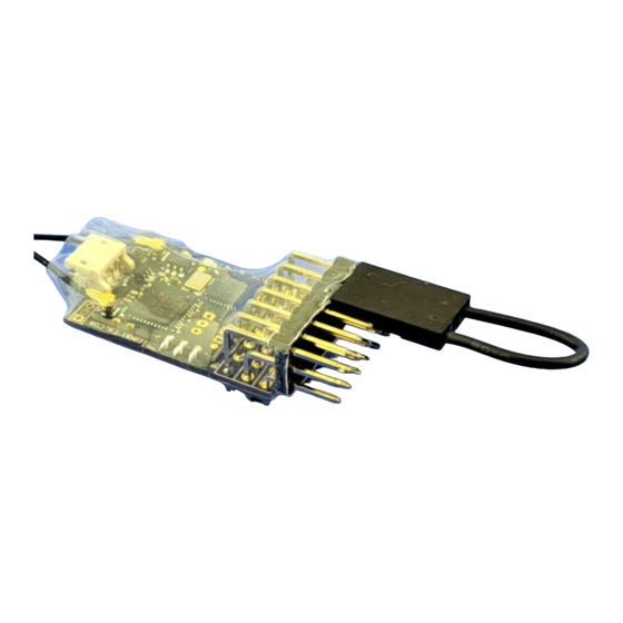
MR001d
is a 2.4GHz DSM2/DSMX 11 output receiver designed for model railway use. It is suitable for
live steam and large battery electric locos. It can be used to drive servos, speed controllers and LEDs.
If purchased with a transmitter, MR001d will be bound to the transmitter and is ready for use;
otherwise, it requires binding to your transmitter. Once bound, the transmitter should be switched on
before the MR001d. If the transmitter is not switched on, MR001d will automatically enter bind mode 5
seconds after switch on; it also be manually bound using a jumper plug on the P5/P7 signal pins.
Usage
Do not bend the receiver circuit board or use with the protective sleeve removed.
Ensure unused pins of P1..P7 cannot contact any metal.
Connect to a battery or ESC output that can provide 3.5V to 8.5V under load. Some servos can
draw a heavy current when starting to move and the voltage of a 'tired' 4 cell NiMH battery may
dip below 3.5V causing MR001d to reset. If this happens, a 5 cell NiMH battery will give better
results. A resettable fuse in the battery positive lead is recommended to protect the battery in the
event of a wiring or component fault. If you need to power from a single LiPo cell (e.g. because of
space reasons), a 5V or 6V booster should be used.
If MR001d has not been supplied configured for your use, set the
Cruise control features as required (see 'Power-On-Changes').
If required, bind to your transmitter (see 'Binding').
Connect your servo(s) or speed controller to the appropriate pins (see
adjust the servo direction and/or travel as required (see
Fix MR001d in place and route the aerial(s) so that it can 'see' the transmitter for best range -
e.g. by routing through a hole in the vehicle body. If the receiver is totally enclosed within a metal
body, the extended aerial version should be used, the last 30mm is the actual aerial. The aerial
should not be cut short or made longer as this will affect operation. It is important to perform a
range check after installation to ensure you have full control of your loco at all positions around
the layout. Double sided foam-cored sticky tape is ideal for mounting the receiver.
Binding
To bind:
1. with transmitter off, switch MR001d on
2. wait for the LED to flash fast
3. switch your transmitter on in bind mode
4. the LED will stop the rapid flash, flash slowly for a while and then
light continuously
5. MR001d is now bound to your transmitter
If the receiver LED does not come on solid (no flash) within 10-15 seconds, the bind process has failed.
This can happen for several reasons and does not normally indicate a fault. If you get a bind fail, try
again after moving the Tx and Rx slightly further apart or changing the relative orientation of the
aerials. Binding is most reliable when no other 2.4GHz transmitters are turned on.
Connections
MR001d has 7 sets of output pins which can be used for servos, speed controllers or LEDs for lighting.
The pin sets, numbered from the top of the diagram below, are 0.1" pitch to take standard R/C plugs.
An additional 4 outputs are available via an optional JST-SH socket at the aerial end of the receiver.
Although the connector has 3.3V and 0V pins, it cannot be used for powering a servo as the 3.3V pin is
Micron R/C, www.micronradiocontrol.co.uk, +44 (0)1653 696008
Uplands House, Castle Howard Road, Malton YO17 6NJ
www.micronradiocontrol.co.uk
+44 (0)1653 696008
throttle
'Servo
Adjustment').
mode, Selecta and
'Connection
Diagrams') and
Manual Bind
Micron MR001d Quick Start Guide : 1 of 4
Advertisement
Table of Contents

Related Manuals for Micron Radio Control MR001d


Summary of Contents for Micron Radio Control MR001d
- Page 1 'Servo Adjustment'). Fix MR001d in place and route the aerial(s) so that it can 'see' the transmitter for best range - e.g. by routing through a hole in the vehicle body. If the receiver is totally enclosed within a metal body, the extended aerial version should be used, the last 30mm is the actual aerial.
- Page 2 Also, there will be no output from P1 until MR001d has received a valid stop throttle signal.
- Page 3 P1..P7 by using a transmitter for adjusting P1..P10 Use of jumper plugs will be described here, see http://micronrc.co.uk/mr001d-info for details on how to use a transmitter to adjust servo throws. WARNING: never place the small jumper across the positive (middle row) and negative (bottom row) pins.
- Page 4 1 and 2 as shown in the image (the black connector in the image is the battery plugged into P4). The standard MR001d setup has servo outputs on P1..P5. If your receiver has servo outputs on P6 and/or P7, these may also be adjusted - P7 requires use of both small and large jumper plugs.
Need help?
Do you have a question about the MR001d and is the answer not in the manual?
Questions and answers