Advertisement
Table of Contents
Micron MR603a Quick Start Guide
This guide is designed to get you started with MR603a as quickly as possible. More information can be
found in the user manual - http://micronrc.uk/mr603a.
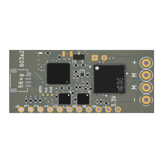
MR603
receiver is 2.4GHz DSM2/DSMX receiver, with 3A max brushed speed controller, for use in
larger scale model rail locomotives and road vehicles. It is compatible with any Spektrum DSM2 or
DSMX transmitter including all of the Micron
If purchased with a transmitter, MR603 will be bound to the transmitter and is ready for use;
otherwise, it requires binding to your transmitter. Once bound, the transmitter should be switched on
before the MR603. If the transmitter is not switched on, MR603 will automatically enter bind mode 10
seconds after switch on; it may also be configured to bind only manually using pads P5 and P6.
Usage
Do not bend the receiver circuit board
Connect the positive and negative input pads to a suitable battery or power supply, via a on/off
switch in the positive lead. A resettable fuse must be placed in the battery positive lead to
protect the battery in the event of a wiring or component fault.
Connect the 'M' pads to your vehicle motor, removing any connections to track pickups. The
motor should be fitted with suppression capacitors to avoid injecting excessive electrical noise into
the receiver; 100nF across the motor terminals and 100nF from each terminal to the motor case.
If symptoms of motor noise interference persists, 10uH chokes in each motor lead usually solves
the problem; the chokes must be rated for the maximum motor current.
Connect any auxiliary circuits to the F and P pads; the 3.3V pads may be used for powering
auxiliary circuits so long as the maximum current drawn is 200mA or less.
Protect the receiver board before applying power for testing. It must not be allowed to touch
anything metal. If MR603 was purchased with the heatshink cover supplied loose, slide this over
the circuit board.
After switching on:
the CPU LED will emit a rapid flash followed by a flash count corresponding to the selected
configuration (default = 1), shown twice
the CPU LED will then slow flash while MR603 is searching for its bound transmitter; if not
already bound, approx 10 seconds later the receiver will go into bind mode and the RF LED
will show a rapid flash; switch your transmitter on in bind mode and the RF LED will show an
irregular slow flash eventually lighting continuously.
When bound:
the CPU LED will be on to show receipt of good data from the transmitter
the RF LED will be on and may flicker due to electrical (e.g motor) noise, signal fades caused
by reflections, interference from WiFi or Bluetooth signals, or overloading from the
transmitter (this will happen if the transmitter is too close)
the CPU LED will show a repeated double flash when deselected (transmitter Selecta switch is
moved)
the CPU LED will show a repeated 5 flash if the low voltage cutoff has triggered
After testing, apply the heatshrink cover if not already fitted.
Fix the receiver in place and route the aerial so that the last 30mm can 'see' the transmitter for
best range - e.g. by routing through a hole in the vehicle body. The aerial should not be cut short
or made longer as this will affect operation. It is important to perform a range check after
installation to ensure you have full control of your loco/vehicle at all positions around the layout.
Double sided foam-cored sticky tape is ideal for mounting the receiver.
Micron R/C, www.micronradiocontrol.co.uk, +44 (0)1653 696008
Uplands House, Castle Howard Road, Malton YO17 6NJ
www.micronradiocontrol.co.uk
+44 (0)1653 696008
model rail
transmitters. The voltage range is 4.5V to 20V.
Micron MR603a Quick Start Guide : 1 of 2
Advertisement
Table of Contents

Subscribe to Our Youtube Channel
Related Manuals for Micron Radio Control MR603a


Summary of Contents for Micron Radio Control MR603a
- Page 1 +44 (0)1653 696008 Micron MR603a Quick Start Guide This guide is designed to get you started with MR603a as quickly as possible. More information can be found in the user manual - http://micronrc.uk/mr603a. MR603 receiver is 2.4GHz DSM2/DSMX receiver, with 3A max brushed speed controller, for use in larger scale model rail locomotives and road vehicles.
- Page 2 The recommended technique is to fill the pad hole with solder and then attach the wire to the top of the pad on the side opposite to the radio board - i.e. don't pass the wire through the pad hole. Micron R/C, www.micronradiocontrol.co.uk, +44 (0)1653 696008 Micron MR603a Quick Start Guide : 2 of 2...
Need help?
Do you have a question about the MR603a and is the answer not in the manual?
Questions and answers