Table of Contents
Advertisement
Quick Links
Advertisement
Table of Contents

Related Manuals for Morgensen MSI200A Series

Summary of Contents for Morgensen MSI200A Series
- Page 1 USER MANUAL MSI200A SERIES INVERTER...
-
Page 3: Preface
The vector control performance of MSI200A series inverters is as outstanding as that of the leading sophisticated inverters on worldwide market. Its speed and torque control can be... -
Page 4: Table Of Contents
Content Preface ................... 2 Content ................... 3 1 Safety Precautions ............... 7 1.1 What this chapter contains ..........7 1.2 Safety definition ..............7 1.3 Warning symbols ............... 7 1.4 Safety guidelines ............... 8 2 Quick Start-up ................11 2.1 What this chapter contains ..........11 2.2 Unpacking inspection ............ - Page 5 5.3 Keypad displaying.............33 5.4 Keypad operation..............33 6 Function Parameters ..............35 6.1 What this chapter contains ..........35 6.2 MSI200A general series function parameters ....35 7 Basic Operation Instruction ............100 7.1 What this chapter contains ..........100 7.2 First powering on ............100 7.3 Vector control..............102 7.4 Torque control ..............103 7.5 Parameters of the motor ..........104 7.6 Start-up and stop control ..........104...
- Page 6 8.6.8 Overcurrent..............119 8.7 Inverter system interference troubleshooting ....119 3....................119 8.8 Maintenance and hardware diagnostics ......120 8.8.1 Overcurrent..............120 8.8.2 Cooling fan ..............122 8.8.3 Capacitors ..............123 8.8.4 Power cable ..............124 9 Communication Protocol ............125 9.1 What this chapter contains ..........125 9.2 Brief instruction to MODBUS protocol ......125 9.3 Application of the inverter ..........125 9.4 RTU command code and communication data illustration 128...
- Page 7 C.6 Reactors ................157 C.7 Filters Filters selection table ...........158 C.8 Braking system ..............158 C.9 Other optional parts ............162 Appendix D Further Information ...........163...
-
Page 8: Safety Precautions
1 Safety Precautions 1.1 What this chapter contains Please read this manual carefully and follow all safety precautions before moving, installing, operating and servicing the inverter. If ignored, physical injury or death may occur, or damage may occur to the devices. If any physical injury or death or damage to the devices occurs for ignoring to the safety precautions in the manual, our company will not be responsible for any damages and we are not legally bound in any manner. -
Page 9: Safety Guidelines
1.4 Safety guidelines Only qualified electricians are allowed to operate on the inverter. Do not carry out any wiring and inspection or changing components when the power supply is applied. Ensure all input power supply is disconnected before wiring and checking and always wait for at least the time designated on the inverter or until the DC bus voltage is less than 36V. - Page 10 The leakage current of the inverter may be above 3.5mA during operation. Ground with proper techniques and ensure the grounding resistor is less than 10Ω. The conductivity of PE grounding conductor is the same as that of the phase conductor (with the same cross sectional area).
- Page 11 1.4.4 What to do after scrapping There are heavy metals in the inverter. Deal with it as industrial effluent.
-
Page 12: Quick Start-Up
MORGENSEN offices. 2. Check the information on the type designation label on the outside of the package to verify that the drive is of the correct type. If not, please contact with local dealers or MORGENSEN offices. -
Page 13: Installation Confirmation
the cabinet. 3. Check that the altitude of the actual usage site is below 1000m. If exceeds, derate1% for every additional 100m. 4. Check that the humidity of the actual usage site is below 90% and condensation is not allowed. If not, add additional protection inverters. 5. -
Page 14: Product Overview
The chapter briefly describes the operation principle, product characteristics, layout, name plate and type designation information. 3.2 Basic principles MSI200A series inverters are wall, flange and mountable devices for controlling asynchronous AC inductance motors. The diagram below shows the main circuit diagram of the inverter. The rectifier converts three- phase AC voltage to DC voltage. -
Page 15: Product Specification
3.3 Product specification Function Specification AC 3PH 220V(-15%)~240V(+10%) Input voltage (V) AC 3PH 380V(-15%)~440V(+10%) AC 3PH 520V(-15%)~690V(+10%) Input Input current (A) Refer to the rated value 50Hz or 60Hz Input frequency (Hz) Allowed range: 47~63Hz Output voltage (V) 0~Input voltage Output current (A) Refer to the rated value Output... -
Page 16: Name Plate
Function Specification resolution 1 channels ( AI2) 0~10V/0~20mA and 1 channel Analog input (AI3) -10~10V Analog output 2 channels (AO1, AO2) 0~10V /0~20mA 8 channels common input, the Max. frequency: 1kHz, internal impedance: 3.3kΩ; Digital input 1 channel high speed input, the Max. frequency: 50kHz 1 channel high speed pulse output, the Max. -
Page 17: Rated Specifications
designation on the type designation label attached to the inverter or the simple name plate. Fig 3-4 Product type Instructions MSI200A : abbreviation of MSI200A 3-digit code: output power. “R” means the decimal point; ”011”:11kW; B, D “015”:15kW G:Constant torque load C, E P:Variable torque load Input voltage degree:... -
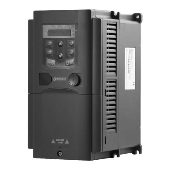
Page 18: Structure Diagram
Constant torque Variable torque Output Input Output Output Input Output Model power current current power current current (kW) (kW) MSI200A -200G/220P-4 MSI200A -220G/250P-4 MSI200A -250G/280P-4 MSI200A -280G/315P-4 MSI200A -315G/350P-4 MSI200A -350G/400P-4 MSI200A -400G-4 MSI200A -500G-4 Note: 1. The input current of 1.5~315kW inverters is measured when the input voltage is 380V and no DC reactor and input/output reactor. - Page 19 Serial Name Illustration Keypad port Connect the keypad Upper cover Protect the internal parts and components See Keypad Operation Procedure for detailed Keypad information See Maintenance and Hardware Fault Diagnose for Cooling fan detailed information Wires port Connect to the control board and the drive board Name plate See Product Overview for detailed information Optional part.
-
Page 20: Installation Guidelines
4 Installation Guidelines 4.1 What this chapter contains The chapter describes the mechanical installation and electric installation. Only qualified electricians are allowed to carry out what described in this chapter. Please operate as the instructions in Safety Precautions. Ignoring these may cause physical injury or death or damage to the devices. - Page 21 The inverter should be installed on an upright position to ensure Installation direction sufficient cooling effect. Note: MSI200A series inverters should be installed in a clean and ventilated environment according to enclosure classification. Cooling air must be clean, free from corrosive materials and electrically conductive dust.
- Page 22 4.2.3 Installation manner The inverter can be installed in two different ways, depending on the frame size: a) Wall mounting (for the inverter≤315kW) b) Flange mounting (for the inverter≤200kW). Some need optional flange installation board. c) Floor mounting (220kW≤the inverter≤500kW). Some need optional base. Fig 4-2 Installation manner (1) Mark the hole location.
- Page 23 4.2.5 Vertical installation Fig 4-4 Vertical installation Note: Windscreen should be added in vertical installation for avoiding mutual impact and insufficient cooling. 4.2.6 Tilt installation Fig 4-5 Tilt installation Note: Ensure the separation of the wind input and output channels in tilt installation for avoiding mutual impact.
-
Page 24: Standard Wiring
4.3 Standard wiring 4.3.1 Wiring diagram of main circuit Fig 4-6 Wring diagram of main circuit Note: The fuse, DC reactor, braking unit, braking resistor, input reactor, input filter, output reactor, output filter are optional parts. Please refer to Peripheral Optional Parts for detailed information. - Page 25 Fig 4-9 18.5kW terminals of main circuit Fig 4-10 22~30kW terminals of main circuit Fig 4-11 37~55 kW terminals of main circuit Fig 4-12 75~110kW terminals of main circuit Fig 4-13 132~200kW terminals of main circuit...
- Page 26 Fig 4-14 220~315kW terminals of main circuit Fig 4-15 350~500kW terminals of main circuit Terminal name Terminal Function ≤30kW ≥37kW 3-phase AC input terminals which are R, S, T Power input of the main circuit generally connected with the power supply.
- Page 27 Terminal name Terminal Function ≤30kW ≥37kW power supply) Note: Do not use an asymmetrically constructed motor cable. If there is a symmetrically constructed grounding conductor in the motor cable in addition to the conductive shield, connect the grounding conductor to the grounding terminal at the inverter and motor ends.
- Page 28 4.3.4 Wiring diagram of control circuit Fig 4-18 Wiring diagram of the control circuit 4.3.5 Terminals of control circuit 0.75~15kW Fig 4-19 Terminals of control circuit Fig 4-20 18.5~500kW Terminals of control circuit Note: the spare terminal is reserved and not be used. Terminal Description...
- Page 29 name +10V Local power supply +10V 1. Input range: AI2 voltage and current can be chose: 0~10V/0~20mA; AI2 can be shifted by J4; AI3:-10V~+10V 2. Input impedance: voltage input: 20kΩ; current input: 500Ω 3. Resolution: the minimum one is 5mV when 10V corresponds to 50Hz 4.
-
Page 30: Layout Protection
4.3.6 Input /Output signal connection figure Please use U-shaped contact tag to set NPN mode or PNP mode and the internal or external power supply. The default setting is NPN internal mode. Fig 4-21 U-shaped contact tag If the signal is from NPN transistor, please set the U-shaped contact tag between +24V and PW as below according to the used power supply. - Page 31 Fig 4-24 Fuse configuration Note: Select the fuse as the manual indicated. The fuse will protect the input power cable from damage in short-circuit situations. It will protect the surrounding devices when the internal of the inverter is short circuited. 4.4.2 Protecting the motor and motor cable in short-circuit situations The inverter protects the motor and motor cable in a short-circuit situation when the motor cable is dimensioned according to the rated current of the inverter.
-
Page 32: Keypad Operation Procedure
• Start-up 5.2 Keypad The keypad is used to control MSI200A series inverters, read the state data and adjust parameters. Fig 5-1 Keypad Note: The keypad of 0.75~15kW as show in Fig 5-1 A, and 18.5~500kW as show in Fig 5-1 B;... - Page 33 Name Description LED for keypad operation, terminals operation and remote communication control LED off means that the inverter is in the keypad operation state; LED blinking LOCAL/REMOT means the inverter is in the terminals operation state; LED on means the inverter is in the remote communication control state.
-
Page 34: Keypad Displaying
Quick key function code P07.02. 5.3 Keypad displaying The keypad displaying state of MSI200A series inverters is divided into stopping state parameter, running state parameter, function code parameter editing state and fault alarm state and so on. Fig 5-2 Displayed state 5.4 Keypad operation... - Page 35 Fig 5-3 Sketch map of modifying parameters 5.4.2 How to set the password of the inverter MSI200A series inverters provide password protection function to users. Set P7.00 to gain the password and the password protection becomes valid instantly after quitting from the function code editing state.
-
Page 36: Function Parameters
This chapter lists and describes the function parameters. 6.2 MSI200A general series function parameters The function parameters of MSI200A series inverters have been divided into 30 groups (P00~P29) according to the function, of which P18~P28 are reserved. Each function group contains certain function codes applying 3-level menus. - Page 37 password. When modify the parameters by serial communication, the function of the password follows the above rules, too. Default Function Name Detailed instruction of parameters Modify value code P00 Group Basic function group 1: Sensorless vector control mode 1 (applying to No need to install encoders.
- Page 38 AI1 setting is not available for the device which is 18.5kW or higer than 18.5kW) 2:Analog AI2 setting 3:Analog AI3 setting Set the frequency by analog input terminals. MSI200A series inverters provide 3 channels B frequency analog input terminals as the standard ○ P00.07...
- Page 39 (function code P00.03) 4:High-speed pulse HDI setting The frequency is set by high-speed pulse terminals. MSI200A series inverters provide 1 channel high speed pulse input as the standard configuration. The pulse frequency range is 0.00~50.00kHz. 100.0% of the high speed pulse input setting corresponds to the maximum frequency in forward direction (P00.03) and -100.0%...
- Page 40 Default Function Name Detailed instruction of parameters Modify value code 8:MODBUS communication setting The frequency is set by MODBUS communication. See P14 for detailed information. 9~11: Reserved Note: A frequency and B frequency can not set as the same frequency reference mode. 0:Maximum output frequency, 100% of B frequency setting corresponds to the maximum B frequency...
- Page 41 Function Name Detailed instruction of parameters Modify value code MSI200A series inverters define four groups of ACC/DEC time which can be selected by P05. Depend ○ P00.12 DEC time 1 The factory default ACC/DEC time of the inverter is the first group.
- Page 42 Default Function Name Detailed instruction of parameters Modify value code Above 75kW 2kHz The advantage of high carrier frequency: ideal current waveform, little current harmonic wave and motor noise. The disadvantage of high carrier frequency: increasing the switch loss, increasing inverter temperature and the impact to the output capacity.
- Page 43 1:P type; for the variable torque load of rated parameters (fans and water pumps) MSI200A series inverters can use G/P type, the available motor power of G type is small one power file than that of P type. 0:No operation...
- Page 44 Default Function Name Detailed instruction of parameters Modify value code limited in the lower limit frequency. Setting range: 0.0~50.0s The braking The inverter will carry out DC braking at the current braking current set before starting and it will ◎ P01.03 0.0% before...
- Page 45 Default Function Name Detailed instruction of parameters Modify value code DEC time of the ending ○ P01.07 0.1s step of S curve 0: Decelerate to stop: after the stop command becomes valid, the inverter decelerates to reduce the output frequency during the set time. When the frequency decreases to 0Hz, the ○...
- Page 46 Default Function Name Detailed instruction of parameters Modify value code rotation the table below: Setting range: 0.0~3600.0s Shifting Set the threshold point of the inverter: between 0:Switch after 0 frequency ◎ P01.14 FWD/REV 1:Switch after the starting frequency rotation 2:Switch after the stopping speed Stopping ◎...
- Page 47 Default Function Name Detailed instruction of parameters Modify value code 1: The terminal running command is valid when powering on. If the running command is detected to be valid during powering on, the system will start the inverter automatically after the initialization.
- Page 48 Default Function Name Detailed instruction of parameters Modify value code restart after powering off and then powering on. power off Setting range: 0.0~3600.0s (valid when P01.21=1) The function determines the brake release after the running command is reference, and the Start delay ○...
- Page 49 Default Function Name Detailed instruction of parameters Modify value code Rotor Depend ○ P02.07 resistor of 0.001~65.535Ω AM 1 model Leakage Depend ○ P02.08 inductance of 0.1~6553.5mH AM 1 model Mutual Depend ○ P02.09 inductance of 0.1~6553.5mH AM 1 model Non-load Depend ○...
- Page 50 Default Function Name Detailed instruction of parameters Modify value code Setting range: 20.0%~120.0% Correct the power displaying of motor 1. Correction Only impact the displaying value other than the coefficient of ● 1.00 P02.28 control performance of the inverter. motor 1 power Setting range: 0.00~3.00 P03 Group...
- Page 51 Default Function Name Detailed instruction of parameters Modify value code The setting range of P03.00:0~200.0 The setting range of P03.01: 0.000~10.000s The setting range of P03.02:0.00Hz~P03.05 The setting range of P03.03:0~200.0 The setting range of P03.04: 0.000~10.000s The setting range of P03.05:P03.02~P00.03(the Max.
- Page 52 Default Function Name Detailed instruction of parameters Modify value code Keypad Setting range: -300.0%~300.0%(rated current of ○ P03.12 setting 50.0% the motor) torque Torque ○ P03.13 reference 0.000~10.000s 0.010s filter time Upper 0:Keypad frequency of (P03.16 sets P03.14,P03.17 sets P03.15) ○...
- Page 53 Default Function Name Detailed instruction of parameters Modify value code source setting is not available for the device which is 18.5kW or higer than 18.5kW) 2: AI2 3: AI3 4: HDI 5:MODBUS communication Note: setting mode 1~9,100% corresponds to three times of the motor current. Keypad setting of ○...
- Page 54 Default Function Name Detailed instruction of parameters Modify value code Weak 0~8000 magnetic ○ P03.26 Note: P03.24~P03.26 are invalid for vector 1000 proportional mode. gain Vector 0: Display the actual value ○ P03.27 control speed 1: Display the setting value Compensatio 0.0~100.0% n coefficient...
- Page 55 Default Function Name Detailed instruction of parameters Modify value code Torque boost is used for the compensation of low frequency torque. P04.01 is relative to the Max. output voltage V P04.02 defines the percentage of closing frequency of manual torque to f Torque boost should be selected according to Motor 1 the load.
- Page 56 Default Function Name Detailed instruction of parameters Modify value code of motor 1 or damage. The inverter may occur the overcurrent speed or overcurrent protection. The setting range of P04.03: 0.00Hz~P04.05 The setting range of P04.04:0.0%~110.0% The setting range of P04.05:P04.03~ P04.07 The setting range of P04.06:0.0%~110.0% (the rated voltage of motor 1) The setting range of P04.07:P04.05~ P02.02...
- Page 57 Default Function Name Detailed instruction of parameters Modify value code setting separation. channel 0: Keypad setting voltage: the output voltage is determined by P04.28. 1:AI1 setting voltage(The inverter(≤15kW) can be set by the analog potentiometer on the keypad and AI1 setting is not available for the device which is 18.5kW or higer than 18.5kW) 2:AI2 setting voltage;...
- Page 58 Default Function Name Detailed instruction of parameters Modify value code power The setting range of P04.33: 1.00~1.30 P05 Group Input terminals 0: HDI is high pulse input. See P05.49~P05.54 ◎ P05.00 HDI input 1: HDI is switch input S1 terminal 0: No function ◎...
- Page 59 Default Function Name Detailed instruction of parameters Modify value code 27:Traverse reset(return to the center frequency) 28:Counter reset 29:Torque control prohibition 30:ACC/DEC prohibition 31:Counter trigger 32:Length reset 33:Cancel the frequency change setting temporarily 34:DC brake 36:Shift the command to the keypad 37:Shift the command to the terminals 38:Shift the command to the communication 39: Pre-exciting command...
- Page 60 Default Function Name Detailed instruction of parameters Modify value code running direction. This mode is widely used. It mode determines the rotation direction by the defined FWD and REV terminals command. 运行命令 停止 正转运行 反转运行 保持 1:2-wire control 2; Separate the enable from the direction.
- Page 61 Default Function Name Detailed instruction of parameters Modify value code 3:3-wire control 2; Sin is the enabling terminal on this mode, and the running command is caused by SB1 or SB3 and both of them control the running direction.NC SB2 generates the stop command.
- Page 62 Default Function Name Detailed instruction of parameters Modify value code delay time terminal ○ P05.17 0.000s switching-off delay time S3 terminal ○ P05.18 switching-on 0.000s delay time terminal ○ P05.19 0.000s switching-off delay time S4 terminal ○ P05.20 switching-on 0.000s delay time terminal ○...
- Page 63 Default Function Name Detailed instruction of parameters Modify value code switching-off delay time terminal ○ P05.28 0.000s switching-on delay time terminal ○ P05.29 0.000s switching-off delay time terminal ○ P05.30 0.000s switching-on delay time terminal ○ P05.31 0.000s switching-off delay time Lower limit of The inverter(≤15kW) can be set by the analog ○...
- Page 64 Default Function Name Detailed instruction of parameters Modify value code g setting of Input filter time: this parameter is used to adjust the upper the sensitivity of the analog input. Increasing the limit of AI2 value properly can enhance the anti-interference of the analog, but weaken the sensitivity of the AI2 input ○...
- Page 65 Default Function Name Detailed instruction of parameters Modify value code setting Upper limit 50.00 ○ P05.52 frequency of P05.50 ~50.00kHz Correspondin g setting of ○ P05.53 upper limit -100.0%~100.0% 100.0% frequency of frequency ○ P05.54 0.000s~10.000s 0.100s input filter time P06 Group Output terminals The function selection of the high-speed pulse...
- Page 66 Default Function Name Detailed instruction of parameters Modify value code 19:Defined count value arrival 20:External fault valid 21:Length arrival 22:Running time arrival 23:MODBUS communication virtual terminals output 26: DC bus voltage establishment 27: Auxiliary motor 1 28: Auxiliary motor 2 The function code is used to set the pole of the output terminal.
- Page 67 Default Function Name Detailed instruction of parameters Modify value code ○ P06.15 AO2 output 1:Setting frequency 2:Ramp reference frequency 3:Running rotation speed 4:Output current (relative to the rated current of the inverter) 5:Output current (relative to the rated current of the motor) 6:Output voltage 7:Output power 9:Output torque...
- Page 68 Default Function Name Detailed instruction of parameters Modify value code to the lower Setting range of P06.18 0.00V~10.00V limit Setting range of P06.19 P06.17~100.0% Setting range of P06.20 0.00V~10.00V Upper limit of ○ P06.24 100.0% Setting range of P06.21 0.000s~10.000s AO2 output Setting range of P06.22 0.0%~P06.24 Correspondin...
- Page 69 Default Function Name Detailed instruction of parameters Modify value code operator can not enter into it. Note: Restoring to the default value can clear the password, please use it with caution. The function code determines the mode of parameters copy. 0:No operation 1:Upload the local function parameter to the keypad...
- Page 70 Default Function Name Detailed instruction of parameters Modify value code does not record the state after shifting during powering off. The inverter will run according to parameter P00.13 during next powering on. When P07.02=6, set the shifting sequence of Shifting running command channels.
- Page 71 Default Function Name Detailed instruction of parameters Modify value code BIT3: HDI frequency BIT4: motor overload percentage (% on) BIT5: the inverter overload percentage (% on) BIT6: ramp frequency given value(Hz on) BIT7: linear speed BIT8: AC inlet current (A on) BIT9: upper limit frequency (Hz on) 0x0000~0xFFFF BIT0:set frequency...
- Page 72 Default Function Name Detailed instruction of parameters Modify value code Converter ● P07.12 module 0~100.0℃ temperature Software ● P07.13 1.00~655.35 version Local ● P07.14 accumulative 0~65535h running time High bit of Display the power used by the inverter. ● P07.15 power The power consumption of the inverter consumption...
- Page 73 Default Function Name Detailed instruction of parameters Modify value code 0:No fault 1:IGBT U phase protection(OUt1) 2:IGBT V phase protection(OUt2) 3:IGBT W phase protection(OUt3) 4:OC1 Current fault 5:OC2 ● P07.27 type 6:OC3 7:OV1 8:OV2 9:OV3 10:UV 11:Motor overload(OL1) 12:The inverter overload(OL2) 13:Input side phase loss(SPI) 14:Output side phase loss(SPO) 15:Overheat of the rectifier module(OH1)
- Page 74 Default Function Name Detailed instruction of parameters Modify value code current fault Output P07.35 voltage at the current fault Output P07.36 current at 0.0A current fault Bus voltage P07.37 at current 0.0V fault The Max. temperature P07.38 0.0℃ at current fault Input terminals...
- Page 75 Default Function Name Detailed instruction of parameters Modify value code fault ● Input terminals P07.47 state at previous fault ● Output terminals P07.48 state at previous fault ● Runnig frequency at P07.49 0.00Hz previous 2 fault ● Output voltage at P07.50 0.00Hz previous 2...
- Page 76 Refer to P00.11 and P00.12 for detailed Depend definition. ○ P08.02 ACC time 3 MSI200A series define four groups of ACC/DEC model time which can be selected by P5 group. The Depend first group of ACC/DEC time is the factory default ○...
- Page 77 Default Function Name Detailed instruction of parameters Modify value code Jumping ○ P08.14 frequency 0.00Hz range 3 Setting range: 0.00Hz ~P00.03 (the Max. frequency) Traverse This function applies to the industries where ○ P08.15 0.0% range traverse and convolution function are required such as textile and chemical fiber.
- Page 78 Default Function Name Detailed instruction of parameters Modify value code The setting range of P08.15: 0.0~100.0% (relative to the set frequency) The setting range of P08.16: 0.0~50.0% (relative to the traverse range) The setting range of P08.17: 0.1~3600.0s The setting range of P08.18: 0.1~3600.0s Setting The function codes of setting length, actual ○...
- Page 79 Default Function Name Detailed instruction of parameters Modify value code Setting range of P08.25:P08.26~65535 Setting range of P08.26:0~P08.25 Pre-set running time of the inverter. When the accumulative running time achieves the set time, Set running ○ P08.27 the multi-function digital output terminals will time output the signal of “running time arrival”.
- Page 80 Default Function Name Detailed instruction of parameters Modify value code (FDT1 electrical level) Setting range of P08.34: 0.00 Hz ~P00.03 (the Max. frequency) Setting range of P08.35: 0.0~100.0% (FDT2 electrical level) When the output frequency is among the below or above range of the set frequency, the multi- function digital output terminal will output the signal of “frequency arrival”, see the diagram below for detailed information:...
- Page 81 Default Function Name Detailed instruction of parameters Modify value code rotates. 1:The fan keeps on running after power on (generally for the site with high temperature and humidity) 0x00~0x21 ◎ LED ones: PWM mode selection 0: PWM mode 1, three-phase modulation and two-modulation 1: PWM mode 2, three-phase modulation LED tens: low-speed carrier frequency limit...
- Page 82 Default Function Name Detailed instruction of parameters Modify value code the stop command LED thousands: ∧/∨ keys and digital potentiometer integral function 0:The integral function is valid 1:The integral function is invalid Integral ratio of the keypad ○ P08.43 0.01~10.00s 0.10s potentiomete 0x00~0x221...
- Page 83 Default Function Name Detailed instruction of parameters Modify value code 0:Save when power off 1:Clear when power off High bit of This parameter is used to set the original value ○ P08.48 initial power of the power consumption. 0° consumption The original value of the power consumption Low bit of =P08.48*1000+ P08.49...
- Page 84 Default Function Name Detailed instruction of parameters Modify value code (≤15kW) can be set by the analog potentiometer on the keypad and AI1 setting is not available for the device which is 18.5kW or higer than 18.5kW) 2:Analog channel AI2 reference 3:Analog channel AI3 set 4:High speed pulse HDI set 5:Multi-step speed set...
- Page 85 Default Function Name Detailed instruction of parameters Modify value code control during wrap-down The function is applied to the proportional gain P of PID input. P determines the strength of the whole PID adjuster. The parameter of 100 means that when Proportional ○...
- Page 86 Default Function Name Detailed instruction of parameters Modify value code stops to work during the deviation limit. Set the function properly to adjust the accuracy and stability of the system. Setting range:0.0~100.0% Output upper These parameters are used to set the upper and ○...
- Page 87 Default Function Name Detailed instruction of parameters Modify value code continuous working and the integration will change with the trend. 1: Stop integral adjustment when the frequency achieves the upper and low limit. If the integration keeps stable, and the trend between the reference and the feedback changes, the integration will change with the trend quickly.
- Page 88 Multi-step speeds are in the range of --f ○ P10.09 0.0s time of step 3 and it can be set continuously. Multi-step MSI200A series inverters can set 16 steps ○ P10.10 0.0% speed 4 speed, selected by the combination of multi-step The running terminals 1~4, corresponding to the speed 0 to ○...
- Page 89 Default Function Name Detailed instruction of parameters Modify value code time of step 8 keypad, analog value, high-speed pulse, PLC, communication frequency input. Select at most Multi-step ○ P10.20 0.0% 16 steps speed via the combination code of S1, speed 9 S2, S3, and S4.
- Page 90 Default Function Name Detailed instruction of parameters Modify value code ACC/DEC BIT5 BIT4 time BIT7 BIT6 BIT9 BIT8 BIT11 BIT10 BIT13 BIT12 BIT15 BIT14 BIT1 BIT0 BIT3 BIT2 BIT5 BIT4 BIT7 BIT6 P10.35 BIT9 BIT8 BIT11 BIT10 BIT13 BIT12 BIT15 BIT14 After the users select the corresponding ACC/DEC time, the combined 16 binary bits will change into decimal bit, and then set the...
- Page 91 Default Function Name Detailed instruction of parameters Modify value code 1: Input phase loss protection enable LED tens: 0: Input phase loss protection disable 1: Input phase loss protection enable LED hundreds: 0: Input phase loss hardware protection disable 1: Input phase loss hardware protection enable Sudden power loss 0: Enable...
- Page 92 Default Function Name Detailed instruction of parameters Modify value code Protection 120~150%(standard bus voltage) (380V) 140% voltage at ○ P11.04 overvoltage stall 120~150%(standard bus voltage) (220V) 120% The actual increasing ratio is less than the ratio Current limit of output frequency because of the big load ◎...
- Page 93 Default Function Name Detailed instruction of parameters Modify value code 120% Setting range of P11.08: Enable and define the overload pre-alarm of the inverter or the motor. Setting range: 0x000~0x131 LED ones: 0:Overload pre-alarm of the motor, comply with the rated current of the motor Overload 1:Overload pre-alarm of the inverter, comply with pre-alarm...
- Page 94 Default Function Name Detailed instruction of parameters Modify value code Select the action of fault output terminals on undervoltage and fault reset. 0x00~0x11 Output LED ones: terminal ○ 0:Action under fault undervoltage P11.13 0x00 action during 1:No action under fault undervoltage fault LED tens: 0:Action during the automatic reset...
- Page 95 Default Function Name Detailed instruction of parameters Modify value code unique in the communication net. This is the fundamental for the point to point communication between the upper monitor and the drive. Note: The address of the slave cannot set to 0. Set the digital transmission speed between the upper monitor and the inverter.
- Page 96 Default Function Name Detailed instruction of parameters Modify value code to the upper monitor. If the answer delay is shorter than the system processing time, then the answer delay time is the system processing time, if the answer delay is longer than the system processing time, then after the system deal with the data, waits until achieving the answer delay time to send the data to the upper...
- Page 97 Default Function Name Detailed instruction of parameters Modify value code Setting Display current set frequency of the inverter ● P17.00 frequency Range: 0.00Hz~P00.03 Output Display current output frequency of the inverter ● P17.01 frequency Range: 0.00Hz~P00.03 Ramp Display current ramp reference frequency of the ●...
- Page 98 Default Function Name Detailed instruction of parameters Modify value code Display the current linear speed of the inverter. ● P17.16 Linear speed Range: 0~65535 Display the current length of the inverter. ● P17.17 Length Range: 0~65535 Display the current counting number of the Counting ●...
- Page 99 Default Function Name Detailed instruction of parameters Modify value code overload ● P17.38 PID output -100.00~100.00% 0.00% Wrong ● P17.39 download of 0.00~99.99 0.00 parameters P24 Group Water supply Water 0: Disabled ◎ supply P24.00 1: Enabled selection 0: AI1 setting value (The inverter(≤15kW) can be set by the analog potentiometer on the Press keypad and AI1 setting is not available for the...
- Page 100 Default Function Name Detailed instruction of parameters Modify value code motor P24.11 Start/stop delay time of ○ 5.0s auxiliary motor 1 P24.12 Start/stop delay time of auxiliary motor 2 P24.10 is used to select the valid auxiliary motor. 0: No auxiliary motor ○...
-
Page 101: Basic Operation Instruction
7 Basic Operation Instruction 7.1 What this chapter contains This chapter describes the internal function mode of the inverter in details. Check all terminals are connected properly and tightly. Check that the power of the motor corresponds to that of the inverter. 7.2 First powering on Check before powering on Please check according to the installation list in chapter two. - Page 102 Note: If fault occurs, please do as the “Fault Tracking”. Estimate the fault reason and settle the issue. Besides P00.01 and P00.02, terminal command setting can also used to set the running command channel.
-
Page 103: Vector Control
This method can realize the decoupling of exciting current and torque current to adjust the high performance of asynchronous motors. MSI200A series inverters are embedded speedless sensor vector control calculation for driving both asynchronous motors and synchronous motors. Because the core calculation of vector control is based on exact motor parameter models, the accuracy of motor parameter will impact on the performance of vector control. -
Page 104: Torque Control
7.4 Torque control MSI200A series inverters support two kinds of control mode: torque control and rotation speed control. The core of rotation speed is that the whole control focuses on the stable speed and ensures the setting speed is the same as the actual running speed. The Max. Load sould be in the range of the torque limit. -
Page 105: Parameters Of The Motor
7.5 Parameters of the motor Physical accident may occur if the motor starts up suddenly during autotune. Please check the safety of surrounding environment of the motor and the load before autotune. The power is still applied even the motor stops running during static autotune. -
Page 106: Frequency Setting
3. The starting logic figure of starting after the automatic fault reset 7.7 Frequency setting MSI200A series inverters can set the frequency by various means. The reference channel can be divided into main reference channel and assistant reference channel. - Page 107 The actual reference of the inverter is consisted of main reference channel and assistant reference channel. MSI200A series inverters support the shifting between different reference channels and the detailed shifting rules is as below: Multi-function Multi-function...
-
Page 108: Simple Plc
PLC finishes a circle (or a step). 7.9 Multi-step speed running Set the parameters when the inverter carries out multi-step speed running. MSI200A series inverters can set 16 step speed which can be selected by the combination code of multi-step... -
Page 109: Pid Control
7.10 PID control PID control is commonly used to control the procedure. Adjust the output frequency by proportional, integral, differential operation with the dispersion of the target signals to stabilize the value on the target. It is possible to apply to the flow, pressure and temperature control. Figure of basic control is as below:... - Page 110 When P00.06, P00. 07=7 or P04.27=6, the running mode of the inverter is procedure PID control. 7.15.1 General steps of PID parameters setting: a Ensure the gain P When ensure the gain P, firstly cancel the PID integration and derivation (set Ti=0 and Td=0, see the PID parameter setting for detailed information) to make proportional adjustment is the only method to PID.
-
Page 111: Pulse Counter
7.11 Pulse counter MSI200A series inverters support pulse counter which can input counting pulse through HDI terminal. When the actual length is longer than or equal to the set length, the digital output terminal can output length arrival pulse signal and the corresponding length will be cleared... -
Page 112: Fault Tracking
Using the information reference in this chapter, most alarm and fault cause can be identified and corrected. If not, contact with the MORGENSEN office. 8.3 How to reset The inverter can be reset by pressing the keypad key STOP/RST, through digital input, or by switching the power light. - Page 113 Fault code Fault type Possible cause What to do Over-current when The voltage of the grid is Select the inverter with a deceleration too low larger power The power of the inverter Check if the load is short is too low circuited (the grounding ...
- Page 114 Fault code Fault type Possible cause What to do Check input power Phase loss or fluctuation Check installation Input phase loss of input R,S,T distribution Check the output U,V,W phase loss input(or distribution Output phase loss serious asymmetrical ...
- Page 115 Fault code Fault type Possible cause What to do Check the PID feedback PID feedback offline signal PIDE PID feedback fault PID feedback source Check the PID feedback disappear source Braking circuit fault or Check the braking unit damage to the braking and change new braking Braking unit fault...
-
Page 116: Common Fault Analysis
Fault code Fault type Possible cause What to do The connection of the Check the keypad wires keypad wires is not good or broken and ensure whether there The keypad wire is too is mistake Parameters Change the hardware and long and affected by downloading fault strong interference... -
Page 117: Motor Vibration
8.6.2 Motor vibration 8.6.3 Overvoltage... -
Page 118: Undervoltage Fault
8.6.4 Undervoltage fault 8.6.5 Abnormal motor heat... -
Page 119: Inverter Overheating
8.6.6 Inverter overheating 8.6.7 Stall during the acceleration of the motor... -
Page 120: Overcurrent
8.6.8 Overcurrent Overcurrent Settle the short circuit Check if UVW is short circuited problem and configure to the earth. Remove the motor the motor cables rightly cable and ensure if there is connected with the earth. Check if the motor is short circuited to the Change the motor earth... -
Page 121: Maintenance And Hardware Diagnostics
Maintenance and hardware diagnostics 8.8.1 Overcurrent If installed in an appropriate environment, the inverter requires very little maintenance. The table lists the routine maintenance intervals recommended by MORGENSEN. Checking Checking part Checking item Criterion method Check the ambient Visual temperature, humidity... - Page 122 Checking Checking part Checking item Criterion method crackles or color- examination changing of the protective layers. Ensure that there is no Visual Terminals seat damage examination Ensure that there is no weeping, color-changing, Visual crackles and cassis examination expansion. Estimate the usage time Ensure the safety valve according to the...
-
Page 123: Cooling Fan
The operating hours can be found through P07.14 (accumulative hours of the inverter). Fan failure can be predicted by the increasing noise from the fan bearings. If the inverter is operated in a critical part of a process, fan replacement is recommended once these symptoms appear. Replacement fans are available from MORGENSEN. -
Page 124: Capacitors
8.8.2.1Replacing the cooling fan Read and follow the instructions in chapter Safety Precautions. Ignoring the instructions would cause physical injury or death, or damage to the equipment. 1. Stop the inverter and disconnect it from the AC power source and wait for at least the time designated on the inverter. -
Page 125: Power Cable
Change electrolytic capacitors if the working hours of electrolytic capacitors in the inverter are above 35000. Please contact with the local MORGENSEN offices or dial our national service hotline (400-700-9997) for detailed operation. 8.8.4 Power cable ... -
Page 126: Communication Protocol
9.1 What this chapter contains This chapter describes the communication protocol of MSI200A series inverters. The MSI200A series inverters provide RS485 communication interface. It adopts international standard MODBUS communication protocol to perform master-slave communication. The user can realize centralized control through PC/PLC, upper control PC, etc. (set the control... - Page 127 9.3.1 RS485 The interface of 2-wire RS485 works on semiduplex and its data signal applies differential transmission which is called balance transmission, too. It uses twisted pairs, one of which is defined as A (+) and the other is defined as B (-). Generally, if the positive electrical level between sending drive A and B is among +2~+6V, it is logic“1”, if the electrical level is among -2V~-6V;...
- Page 128 The MODBUS minimum idle time between frames should be no less than 3.5 bytes. The network device is detecting, even during the interval time, the network bus. When the first field (the address field) is received, the corresponding device decodes next transmitting character.
-
Page 129: Rtu Command Code And Communication Data Illustration
The definition of odd checkout: add an odd check bit before the data transmission to illustrate the number of “1” in the data transmission is odd number or even number. When it is odd, the check byte is “0”, otherwise, the check byte is”1”. This method is used to stabilize the parity of the data. - Page 130 depends on the “data number” in the command code. Max. continuous reading number is 16 and the parameter address should be continuous. The byte length of every data is 2 (one word). The following command format is illustrated by hex (a number with “H” means hex) and one hex occupies one byte.
- Page 131 T1-T2-T3-T4 (transmission time of 3.5 bytes) The meaning of the response is that: ADDR = 01H means the command message is sent to the inverter with the address of 01H and ADDR occupies one byte CMD=03H means the message is received from the inverter to the master for the response of reading command and CMD occupies one byte “Byte number”...
- Page 132 T1-T2-T3-T4 (transmission time of 3.5 bytes) Note: section 10.2 and 10.3 mainly describe the command format, and the detailed application will be mentioned in 10.8 with examples. 9.4.3 Command code 08H for diagnosis Meaning of sub-function codes Sub-function Code Description 0000 Return to inquire information data For example: The inquiry information string is same as the response information string when...
- Page 133 High bit of write data Low bit of write data High bit of data number Low bit of data number Byte number High bit of data 0004H Low bit of data 0004H High bit of data 0005H Low bit of data 0005H Low bit of CRC High bit of CRC T1-T2-T3-T4 (transmission time of 3.5 bytes)
- Page 134 Note: P29 group is the factory parameter which can not be read or changed. Some parameters can not be changed when the inverter is in the running state and some parameters can not be changed in any state. The setting range, unit and relative instructions should be paid attention to when modifying the function code parameters.
- Page 135 Function Address Data meaning instruction instruction definition characteristics corresponds to the 100.0% of the rated current of the motor) The upper limit frequency setting during 2005H forward rotation(0~Fmax(unit: 0.01Hz)) The upper limit frequency setting during 2006H reverse rotation(0~Fmax(unit: 0.01Hz)) The upper limit torque of electromotion torque 2007H (0~3000, 1000 corresponds to the 100.0% of the rated current of the motor)
- Page 136 Function Address Data meaning instruction instruction definition characteristics Bit5~ Bit6:=00:keypad control =01:terminal control =10:commuincation control Fault code of the 2102H See the fault type instruction inverter Identifying code 2103H MSI200A -----0x010C of the inverter Operation 3000H Range: 0.00Hz~P00.03 frequency Setting 3001H Range: 0.00Hz~P00.03 frequency...
- Page 137 “communication control command” is writing chrematistics and control the inverter with writing command (06H). R characteristic can only read other than write and W characteristic can only write other than read. Note: when operate on the inverter with the table above, it is necessary to enable some parameters.
- Page 138 After the inverter receives the command, it will change 50 into 5 according to the fieldbus ratio value and then set the hibernation restore delay time as 5s. Another example, after the upper monitor sends the command of reading the parameter of hibernation restore delay time ,if the response message of the inverter is as following: Because the parameter data is 0032H (50) and 50 divided by 10 is 5, then the hibernation restore delay time is 5s.
- Page 139 Code Name Meaning changed during running When the upper monitor is writing or reading and the user Password password is set without password unlocking, it will report that the protection system is locked. The slave uses functional code fields and fault addresses to indicate it is a normal response or some error occurs (named as objection response).
- Page 140 If the response message is as below: The data content is 0003H. From the table 1, the inverter stops. Watch “the current fault type” to “the previous 5 times fault type” of the inverter through commands, the corresponding function code is P07.27~P07.32 and corresponding parameter address is 071BH~0720H(there are 6 from 071BH).
- Page 141 If the operation is successful, the response may be as below (the same with the command sent by the master): Note: the blank in the above command is for illustration. The blank can not be added in the actual application unless the upper monitor can remove the blank by themselves. Common communication fault Common communication faults are: no response to the communication or the inverter returns abnormal fault.
- Page 142 Example 2: set the ACC time of 01H inverter as 10s and the DEC time as 20s ACC time means the time needed if the inverter Depend ○ P00.11 ACC time 1 speeds up from 0Hz to the Max. One (P00.03). DEC time means the time needed if the inverter model speeds down from the Max.
-
Page 143: Appendix A Technical Data
Appendix A Technical Data A.1 What this chapter contains This chapter contains the technical specifications of the inverter, as well as provisions for fulfilling the requirements for CE and other marks. A.2 Ratings A.2.1 Capacity Inverter sizing is based on the rated motor current and power. To achieve the rated motor power reference in the table, the rated current of the inverter must be higher than or equal to the rated motor current. -
Page 144: Electric Power Network Specification
2000…3000 m, the derating is 1% for every 100 m. A.2.2.3 Carrier frequency derating For MSI200A series inverters, different power level corresponds to different carrier frequency range. The rated power of the inverter is based on the factory carrier frequency, so if it is above the factory value, the inverter needs to derate 20% for every additional 1 kHz carrier frequency. -
Page 145: Emc Regulations
Safety of machinery-safety related parts of control systems - EN ISO 13849-1: 2008 Part 1: general principles for design Safety of machinery. Electrical equipment of machines. Part 1: IEC/EN 60204-1:2006 General requirements. Safety of machinery – Functional safety of safety-related IEC/EN 62061: 2005 electrical, electronic and programmable electronic control systems... - Page 146 A.6.1 Category C2 The emission limits are complied with the following provisions: 1. The optional EMC filter is selected according to the options and installed as specified in the EMC filter manual. 2. The motor and control cables are selected as specified in this manual. 3.
-
Page 147: Appendix B Dimension Drawings
Appendix B Dimension Drawings B.1 What this chapter contains Dimension drawings of the MSI200A are shown below. The dimensions are reference in millimeters and inches. B.2 Keypad structure B.2.1 Structure chart keyboard without bracket mounting hole size B.2.2 Installation chart Note: The external keypad can be fix by M3 screws directly or the installation bracket. -
Page 148: Inverter Chart
B.3 Inverter chart B.3.1 Wall mounting 0.75-15kW wall mounting 18.5-30kW wall mounting 37-110kW wall mounting 132-200kW wall mounting... - Page 149 220-315kW wall mounting Installation dimension (unit: mm) Installation Model hole 0.75kW ~2.2kW 174.5 4kW~5.5kW 243.5 7.5kW~15kW 303.5 18.5kW 22kW~30kW 37kW~55kW 75kW~110kW 132kW~200kW 220kW~315kW 379.5 B.3.2 Flange mounting 0.75-15kW flange mounting 18.5-30kW flange mounting...
- Page 150 37-110kW flange mounting 132-200kW flange mounting Installation dimension (unit: mm) Installation Model hole 0.75kW~2.2kW 150.2 115 190 13.5 65.5 4kW~5.5kW 170.2 131 84.5 7.5kW~15kW 191.2 151 11.5 196.3 18.5kW 22kW~30kW 37kW~55kW 261 65.5 75kW~110kW 317 58.5 132kW~200kW 500 178.5...
- Page 151 B.3.3 Floor mounting 220-315kW floor mounting 50-500kW floor mounting Installation Model hole 220kW~315kW 1410 1390 13\12 350kW~500kW 1700 1678 22\12...
-
Page 152: Appendix C Peripheral Options And Parts
Appendix C Peripheral Options and Parts C.1 What this chapter contains This chapter describes how to select the options and parts of MSI200A series. C.2 Peripheral wiring Below is the peripheral wiring of MSI200A series inverters. Note: The inverters (≤15kW) have standard film keypad and the inverters (≥18.5kW) have standard LED keypad. -
Page 153: Power Supply
Pictures Name Descriptions This device is used to improve the power Input reactor factor of the input side of the inverter and control the higher harmonic current. The inverter above 37kW (including DC reactor 37kW) can be connected with DC reactor. Control the electromagnetic interference generated from the inverter, please install Input filter... - Page 154 A symmetrical shielded motor cable (see the figure below) must be used to meet the EMC requirements of the CE. A four-conductor system is allowed for input cabling, but a shielded symmetrical cable is recommended. Compared to a four-conductor system, the use of a symmetrical shielded cable reduces electromagnetic emission of the whole drive system as well as motor bearing currents and wear.
- Page 155 limiting circuits inside the drive which cut down the testing voltage automatically. Check the insulation of the input power cable according to local regulations before connecting to the drive. Note: Check the insulation of the input power cables according to local regulations before connecting the cables.
-
Page 156: Breaker, Electromagnetic Contactor And Leakage Protection
C.4.3 Routing the cables Route the motor cable away from other cable routes. Motor cables of several drives can be run in parallel installed next to each other. It is recommended that the motor cable, input power cable and control cables are installed on separate trays. Avoid long parallel runs of motor cables with other cables to decrease electromagnetic interference caused by the rapid changes in the drive output voltage. - Page 157 It is necessary to add fuse for the avoidance of overload. It is appropriate to use a breaker (MCCB) which complies with the inverter power in the 3- phase AC power and input power and terminals (R, S and T). The capacity of the inverter should be 1.5-2 times of the rated current.
- Page 158 C.6 Reactors If the distance between the inverter and the motor is longer than 50m, frequent overcurrent protection may occur to the inverter because of high leakage current caused by parasitic capacitance effects from the long cables to the ground. In order to avoid the damage of the motor insulation, it is necessary to add reactor compensation.
- Page 159 C.7 Filters Filters selection table The inverter Input filter Output filter MSI200A -0R7G-4 MSI200A -1R5G-4 FLT-P04006L-B FLT-L04006L-B MSI200A -2R2G-4 MSI200A -004G/5R5P-4 FLT-P04016L-B FLT-L04016L-B MSI200A -5R5G/7R5P-4 MSI200A -7R5G/011P-4 FLT-P04032L-B FLT-L04032L-B MSI200A -011G/015P-4 MSI200A -015G/018P-4 FLT-P04045L-B FLT-L04045L-B MSI200A -018G/022P-4 MSI200A -022G/030P-4 FLT-P04065L-B FLT-L04065L-B MSI200A -030G/037P-4 MSI200A -037G/045P-4...
- Page 160 Incorrect wiring may cause damage to the inverter or other devices. MSI200A series inverters below 30kW (including 30kW) need internal braking units and the inverters above 37kW need external braking unit. Please select the resistance and power of the braking resistors according to actual utilization.
- Page 161 The consumed power of the 100% of Mini braking resistor Braking unit braking Braking The inverter type rate Resistor (Ω) (Ω) braking braking braking MSI200A -030G/037P- MSI200A -037G/045P- DBU100H-060-4 11.7 MSI200A -045G/055P- MSI200A -055G/075P- DBU100H-110-4 MSI200A -075G/090P- MSI200A -090G/110P- DBU100H-160-4 MSI200A -110G/132P- MSI200A -132G/160P- DBU100H-220-4...
- Page 162 Never use a brake resistor with a resistance below the minimum value specified for the particular drive. The drive and the internal chopper are not able to handle the overcurrent caused by the low resistance. Increase the power of the braking resistor properly in the frequent braking situation (the frequency usage ratio is more than 10%).
- Page 163 Optimal for 1.5~30kW inverters ands standard for 37~500kW inverters Protect the internal circuit in serious environment. Derate when selecting Side cover the cover. Please contact MORGENSEN for detailed information. Support several languages, parameters copy, high-definition LCD Keypad display and the installation dimension is compatible with the LED keypad.
- Page 164 D.1 Product and service inquirie Address any inquiries about the product to your local MORGENSEN offices, quoting the type designation and serial number of the unit in question. A listing of MORGENSEN sales, support and service contacts can be found by navigating to www.morgensen.de.
- Page 167 MORGENSEN Tel: +49-174-240-9016 Tel / Fax: +49-322-264-88928 e-mail: info@Morgensen.de http://www.Morgensen.de...
- Page 168 WWW.MORGENSEN.DE...
Need help?
Do you have a question about the MSI200A Series and is the answer not in the manual?
Questions and answers