Advertisement
Quick Links
Advertisement

Related Manuals for Morgensen MSI350 Series

Summary of Contents for Morgensen MSI350 Series
- Page 1 USER MANUAL MSI350 SERIES INVERTER...
- Page 3 This operation manual presents installation wiring, parameter setup, fault diagnosis and trouble shooting, and precautions related to daily maintenance. Read through this manual carefully before installation to ensure MSI350 series inverter is installed and operated in a proper manner to give full play to its excellent performance and powerful functions.
- Page 4 Contains Safety precautions ______________________________________ 13 1.1 What this chapter contains _______________________________ 13 1.2 Safety definition _______________________________________ 13 1.3 Warning symbols ______________________________________ 13 1.4 Safety guidelines ______________________________________ 14 1.4.1 Delivery and installation _____________________________ 15 1.4.2 Commissioning and running _________________________ 16 1.4.3 Maintenance and component replacement ______________ 17 1.4.4 What to do after Scrapping __________________________ 17 Quick startup ___________________________________________ 18 2.1 What this chapter contains _______________________________ 18...
- Page 5 3.6 Rated value __________________________________________ 26 3.6.1 AC 3PH 380V(-15%)–440V(+10%) rated value ___________ 26 3.6.2 AC 3PH 520V (-15%)–690V (+10%) rated value __________ 27 3.7 Structure diagram ______________________________________ 28 Installation guide ________________________________________ 29 4.1 What this chapter contains _______________________________ 29 4.2 Mechanical installation __________________________________ 29 4.2.1 Installation environment _____________________________ 29 4.2.2 Installation direction ________________________________ 30 4.2.3 Installation mode __________________________________ 31...
- Page 6 5.1 What this chapter contains _______________________________ 49 5.2 Keypad introduction ____________________________________ 49 5.3 Keypad display ________________________________________ 53 5.4 Stop parameter display state _____________________________ 53 5.5 Running parameter display state __________________________ 54 5.6 Fault alarm display state _________________________________ 54 5.7 Keypad operation ______________________________________ 55 5.7.1 Enter/exit menu ___________________________________ 55 5.7.2 List edit _________________________________________ 60 5.7.3 Add parameters to the parameter list displayed in stop/running...
- Page 7 5.8.9 Analog input_____________________________________ 109 5.8.10 Analog output __________________________________ 112 5.8.11 Digital input ___________________________________ 116 5.8.12 Digital output __________________________________ 123 5.8.13 Simple PLC ___________________________________ 128 5.8.14 Multi-step speed running _________________________ 130 5.8.15 PID control ____________________________________ 132 5.8.16 Run at wobbling frequency _______________________ 137 5.8.17 Local encoder input _____________________________ 139 5.8.18...
- Page 8 7.6.4 Undervoltage ____________________________________ 263 7.6.5 Unusual heating of motor __________________________ 264 7.6.6 Inverter overheating _______________________________ 265 7.6.7 Motor stalls during ACC ____________________________ 266 7.6.8 Overcurrent _____________________________________ 267 7.7 Countermeasures on common interference _________________ 268 7.7.1 Interference on meter switches and sensors ____________ 268 7.7.2 Interference on communication ______________________ 269 7.7.3 Failure to stop and indicator shimmering due to motor cable coupling _____________________________________________ 270...
- Page 9 9.4 RTU command code and communication data _______________ 286 9.4.1 Command code: 03H, reading N words (continuously reading a maximum of 16 words) __________________________________ 286 9.4.2 Command code: 06H, writing a word _________________ 287 9.4.3 Command code: 08H, diagnosis _____________________ 288 9.4.4 Command code: 10H, continuous writing ______________ 289 9.4.5 Data address definition ____________________________ 290 9.4.6 Fieldbus scale ___________________________________ 294...
- Page 10 A.6.3 Ethernet communication card––EC-TX504 ______________ 333 A.6.4 PROFIBUS-DP communication card––EC-TX503 ________ 334 A.6.5 PROFINET communication card——EC- TX509 _________ 336 A.7 Programmable extension card function description ___________ 339 A.7.1 Programmable extension card––EC-PC501-00 __________ 339 Appendix B Technical data ___________________________________ 342 B.1 What this chapter contains ______________________________ 342 B.2 Derated application ___________________________________ 342 B.2.1 Capacity ________________________________________ 342 B.2.2 Derating _________________________________________ 342...
- Page 11 C.4.1 Wall-mounting dimensions __________________________ 349 C.4.2 Flange installation dimensions _______________________ 351 C.4.3 Floor installation dimensions _________________________ 353 C.5 Dimensions of Inverters of AC 3PH 520V (-15%)–690V (+10%) _ 354 C.5.1 Wall-mounting dimensions __________________________ 354 C.5.2 Flange installation dimensions _______________________ 355 C.5.3 Floor installation dimensions _________________________ 356 Appendix D Dimension drawings ______________________________ 358 D.1 What this chapter contains ______________________________ 358...
- Page 12 E.3 STO function installation checklist ________________________ 382 Appendix F Acronyms and abbreviations ________________________ 383 Appendix G Further information _______________________________ 385 G.1 Product and service queries ____________________________ 385 G.2 Feedback on MORGENSEN inverter manuals ______________ 385 G.3 Documents on the internet ______________________________ 385...
- Page 13 1. Safety precautions 1.1 What this chapter contains Read this manual carefully and follow all safety precautions before moving, installing, operating and servicing the inverter. If these safety precautions are ignored, physical injury or death may occur, or damage may occur to the equipment. If any physical injury or death or damage to the equipment occur due to neglect of the safety precautions in the manual, our company will not be responsible for any damages and we are not legally bound in any manner.
- Page 14 Symbols Name Instruction Abbreviation As high voltage still presents in the bus capacitor after power off, wait for at Electric least five minutes (or 15 min / 25 min, shock depending on the warning symbols on the machine) after power off to prevent electric shock Read Read the operation manual before...
- Page 15 1.4.1 Delivery and installation Install the inverter on fire-retardant material and keep the inverter away from combustible materials. Connect the optional brake parts (brake resistors, brake units or feedback units) according to the wiring diagram. Do not operate on a damaged or incomplete inverter. ...
- Page 16 1.4.2 Commissioning and running Disconnect all power sources applied to the inverter before terminal wiring, and wait for at least the time designated on the inverter after disconnecting the power sources. High voltage presents inside the inverter during running. Do not carry out any operation on the inverter during running except for keypad setup.
- Page 17 1.4.3 Maintenance and component replacement Only well-trained and qualified professionals are allowed to perform maintenance, inspection, and component replacement on the inverter. Disconnect all the power sources applied to the inverter before terminal wiring, and wait for at least the time designated on the inverter after disconnecting the power sources.
- Page 18 Check whether the nameplate of the inverter is consistent with the model identifier on the exterior surface of the packing box. If not, contact local dealers or MORGENSEN offices. Check whether the accessories (including user's manual, control keypad and extension card units) inside the packing box are complete.
- Page 19 Application confirmation Check the following items before operating on the inverter. Verify the load mechanical type to be driven by the inverter, and check whether overload occurred to the inverter during actual application, or whether the inverter power class needs to be enlarged? Check whether the actual running current of load motor is less than rated inverter current.
- Page 20 capacity. Check whether the inverter is installed on fire-retardant materials; check whether the hot parts (reactors, brake resistors, etc.) are kept away from combustible materials. Check whether all the control cables are routed separately with power cables based on EMC requirement.
- Page 21 Basic principle MSI350 series inverter is used to control asynchronous AC induction motor and permanent-magnet synchronous motor. The figure below shows the main circuit diagram of the inverter. The rectifier converts 3PH AC voltage into DC voltage, and the capacitor bank of intermediate circuit stabilizes the DC voltage.
- Page 22 Fig 3.3 380V (132kW and above) main circuit diagram Fig 3.4 660V main circuit diagram Note: 132kW and above inverters can be connected to external DC reactors. Before connection, it is required to take off the copper bar between P1 and (+). 132kW and above inverters can be connected to external brake unit.
- Page 23 Product specification Function description Specification AC 3PH 380V (-15%)–440V (+10%) rated voltage: 380V Input voltage (V) AC 3PH 520V (-15%)–690V (+10%) rated voltage: 660V Power input Input current (A) Refer to Rated value Input frequency (Hz) 50Hz or 60Hz, allowable range: 47–63Hz Output voltage (V) 0–input voltage Output current (A)
- Page 24 Function description Specification Terminal analog input No more than 20mV resolution Terminal digital input No more than 2ms resolution Analog input 2 inputs, AI1: 0–10V/0–20mA; AI2: -10–10V Analog output 1 output, AO1: 0–10V /0–20mA Four regular inputs; max. frequency: 1kHz; internal impedance: 3.3kΩ...
- Page 25 3.4 Product nameplate Fig 3.5 Product nameplate Note: This is an example of the nameplate of standard MSI350 products. The CE/TUV/IP20 marking on the top right will be marked according to actual certification conditions. Scan the QR code on the bottom right to download mobile APP and operation manual. Type designation key The type designation key contains product information.
- Page 26 Field Sign Description Contents Brake unit is not included in standard configuration of 380V 45–110kW models (optional built-in brake unit is available, suffix "-B" indicates optional built-in brake unit, eg MSI350-045G-4-B) Rated value 3.6.1 AC 3PH 380V(-15%)–440V(+10%) rated value Product model Output power (kW) Input current (A) Output current (A)
- Page 27 The input current of 1.5–500kW inverter is measured in cases where the input voltage is 380V without additional reactors; The rated output current is the output current when the output voltage is 380V; Within allowable input voltage range, the output current/power cannot exceed rated output current/power.
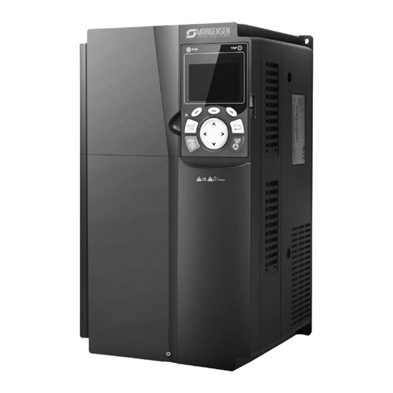
- Page 28 current/power. Structure diagram The inverter layout is shown in the figure below (take a 380V 30kW inverter as an example). Fig 3.7 Structure diagram Name Instruction Upper cover Protect internal components and parts Keypad See details at chapter 5.4 Keypad operation Lower cover Protect internal components and parts Extension card...
- Page 29 Installation must be designed and done according to applicable local laws and regulations. MORGENSEN does not assume any liability whatsoever for any installation which breaches local laws and regulations. If recommendations given by MORGENSEN are not followed, the inverter may experience problems that the warranty does not cover. Mechanical installation 4.2.1...
- Page 30 Install the inverter vertically to ensure good heat dissipation effect direction Note: 1. MSI350 series inverter should be installed in a clean and well-ventilated environment based on the IP level. 2. The cooling air must be clean enough and free from corrosive gases and conductive dust.
- Page 31 Fig 4.1 Installation direction of the inverter 4.2.3 Installation mode There are three kinds of installation modes based on different inverter dimensions. Wall-mounting: suitable for 380V 315kW and below inverters, and 660V 355kW and below inverters; Flange-mounting: suitable for 380V 200kW and below inverters, and 660V 220kW and below inverters;...
- Page 32 4.2.4 Single-unit installation Fig 4.3 Single-unit installation Note: The min. dimension of B and C is 100mm. 4.2.5 Multiple-unit installation Fig 4.4 Parallel installation...
- Page 33 Note: When users install inverters in different sizes, align the top of each inverter before installation for the convenience of future maintenance. The min. dimension of B, D and C is 100mm.
- Page 34 4.2.6 Vertical installation Fig 4.5 Vertical installation...
- Page 35 Note: During vertical installation, users must install windshield, otherwise, the inverter will experience mutual interference, and the heat dissipation effect will be degraded. 4.2.7 Tilted installation Fig 4.6 Tilted installation Note: During tilted installation, it is a must to ensure the air inlet duct and air outlet duct are separated...
- Page 36 from each other to avoid mutual interference. Standard wiring of main circuit 4.3.1 Wiring diagram of main circuit 4.3.1.1 AC 3PH 380V(-15%)–440V(+10%) main circuit wiring diagram Fig 4.7 Main circuit wiring diagram for AC 3PH 380V(-15%)–440V(+10%)
- Page 37 Note: The fuse, DC reactor, brake unit, brake resistor, input reactor, input filter, output reactor and output filter are optional parts. See Appendix D Optional peripheral accessories for details. P1 and (+) have been short connected by default for 380V 132kW and above inverters. If users need to connect to external DC reactor, take off the short-contact tag of P1 and (+).
- Page 38 Fig 4.10 3PH 380V 30-37kW Fig 4.11 3PH 380V 45-110kW Fig 4.12 660V 22–45kW...
- Page 39 Fig 4.13 660V 55–132kW Fig 4.14 380V 132–200kW and 660V 160–220kW...
- Page 40 Fig 4.15 380V 220–315kW and 660V 250–355kW...
- Page 41 Fig 4.16 380V 355–500kW and 660V 400–630kW Terminal name Terminal 380V 132kW and 380V 45- Function description 380V 37kW and sign above 110kW below 660V (inclusive) 3PH AC input terminal, connect to R, S, T Main circuit power input the grid 3PH AC output terminal, connect U, V, W Inverter output...
- Page 42 Terminal name Terminal 380V 132kW and 380V 45- Function description 380V 37kW and sign above 110kW below 660V (inclusive) brake unit terminal Brake unit terminal 2 PB and (+) connect to external Brake resistor Null brake resistor terminal terminal 2 Grounding terminal safe...
- Page 43 4.4 Standard wiring of control circuit 4.4.1 Wiring diagram of basic control circuit Fig 4.18 Wiring diagram of control circuit Terminal Instruction name +10V The inverter provides +10.5V power Input range: AI1 voltage/current can choose 0–10/ 0–20mA; AI2: -10V–+10V voltage; Input impedance: 20kΩ...
- Page 44 Terminal Instruction name Resolution ratio: When 10V corresponds to 50Hz, the min. resolution ratio is 5mV; 25°C, When input above 5V or 10mA, the error is ±0.5% +10.5V reference zero potential Output range: 0–10V voltage or 0–20mA current Voltage or current output is set by toggle switch SW2; 25°C, when input above 5V or 10mA, the error is ±0.5%.
- Page 45 Terminal Instruction name Supports quadrature encoder input; equipped with speed-measurement function +24V—H1 STO input 1 Safe torque off (STO) redundant input, connect to external NC contact, STO acts when the contact opens, and the inverter stops output; Safety input signal wires use shielded wire whose length is within 25m;...
- Page 46 Fig 4.20 NPN mode If input signal comes from PNP transistor, set the U-type short-contact tag based on the power used according to the figure below. Fig 4.21 PNP mode 4.5 Wiring protection 4.5.1 Protect the inverter and input power cable in short-circuit Protect the inverter and input power cable during short-circuit to avoid thermal overload.
- Page 47 Fig 4.22 Fuse configuration Note: Select the fuse according to operation manual. During short-circuit, the fuse will protect input power cables to avoid damage to the inverter; when internal short-circuit occurred to the inverter, it can protect neighboring equipment from being damaged. 4.5.2 Protect the motor and motor cable in short circuit If the motor cable is selected based on rated inverter current, the inverter will be able to protect the...
- Page 48 If frequent switch-over is needed, users can use the switch which carries mechanical interlock or a contactor to ensure motor terminals will not be connected to input power cables and inverter output ends simultaneously.
- Page 49 This chapter tells users how to use the inverter keypad and the commissioning procedures for common functions of the inverter. Keypad introduction LCD keypad is included in the standard configuration of MSI350 series inverter. Users can control the inverter start/stop, read state data and set parameters via keypad. Fig 5.1 Keypad diagram...
- Page 50 When extending the keypad cable to install the keypad, M3 screws can be used to fix the keypad onto the door plate, or optional keypad installation bracket can be used. If you need install the keypad on another position rather than on the inverter, use a keypad extension cable with a standard RJ45 crystal head.
- Page 51 No. Name Instruction the default function of short-cut key (7) is The function of confirmation key varies with Confirmation menus, eg confirming parameter setup, confirming parameter selection, entering the next menu, etc. Under keypad operation mode, the running key is used for running operation or Running key autotuning operation.
- Page 52 Header C and model display Inverter model display: "MSI350" – current inverter is area MSI350 series inverter The parameter name Display the parameter name and corresponding function code and function code monitored by the inverter; three monitoring parameters can be...
- Page 53 (6) interfaces, and the contents displayed in this area is also different Keypad display The display state of MSI350 series keypad is divided into stop parameter display state, running parameter display stateand fault alarm display state. Stop parameter display state When the inverter is in stop state, the keypad displays stop state parameters, and this interface is the main interface during power-up by default.
- Page 54 stop display parameter list can also be deleted or shifted. 5.5 Running parameter display state After receiving valid running command, the inverter will enter running state, and the keypad displays running state parameter with RUN indicator on the keypad turning on. Under running state, multiple kinds of state parameters can be displayed.
- Page 55 Fig 5.7 Fault alarm display state 5.7 Keypad operation Various operations can be performed on the inverter, including entering/exiting menu, parameter selection, list modification and parameter addition. 5.7.1 Enter/exit menu Regarding the monitoring menu, the operation relation between enter and exit is shown below. Fig 5.8 Enter/exit menu diagram 1 Regarding the system menu, the operation relation between enter and exit is shown below.
- Page 56 Fig 5.9 Enter/exit menu diagram 2 The keypad menu setup is shown as below. First-level Second-level Third-level Fourth-level Common P00.10: Set frequency via keypad...
- Page 57 First-level Second-level Third-level Fourth-level parameter P00.00: Speed control mode setup Pxx.xx : Common parameter setup Quick setup for function Pxx.xx code P00: Basic function group P00.xx P07: HMI group P07.xx P08: Enhance function group P08.xx Basic P11: Protection parameter parameter P11.xx group group setup...
- Page 58 First-level Second-level Third-level Fourth-level P15: Communication extension card 1 function P15.xx group P16: Communication extension card 2 function P16.xx group Optional card P25: Extension I/O card input function group P25.xx setup function group P26: Extension I/O card P26.xx output function group P27: PLC function group P27.xx P28: Master/slave function...
- Page 59 First-level Second-level Third-level Fourth-level P07.33: Running frequency of present fault P07.34: Ramps frequency Fault state present fault P07.xx: xx state of the last but xx fault Clear fault Ensure to clear fault history? history Pxx.xx has modified parameter 1 Modified Pxx.xx has modified parameter 2 parameter Pxx.xx has modified parameter xx...
- Page 60 First-level Second-level Third-level Fourth-level Fault time enable Control board burning selection 5.7.2 List edit The monitoring items displayed in the parameter list of stop state can be added by users as needed (through the menu of the function code in state check group), and the list can also be edited by users eg "shift up", "shift down"...
- Page 61 including delete, shift-up and shift-down; the addition function can be set in a certain function code of a function group. The edit function is shown in the figure below. Fig 5.12 List edit diagram 3 5.7.3 Add parameters to the parameter list displayed in stop/running state In the fourth-level menu of "State monitoring", the parameters in the list can be added to the "parameter displayed in stop state"...
- Page 62 state" list or "parameter displayed in running state" list; All the parameters in P17, P18 and P19 group can be added to the "parameter displayed in stop state" list or "parameter displayed in running state" list. Up to 16 monitoring parameters can be added to the "parameter displayed in stop state" list; and up to 32 monitoring parameters can be added to the "parameter displayed in running state"...
- Page 63 current value will be highlighted automatically. After parameter selection is done, press key or key to save the selected parameter and return to the previous menu. In parameter selection edit interface, press key to maintain the parameter value and return to the previous menu. Fig 5.15 Parameter selection edit interface In parameter selection edit interface, the "authority"...
- Page 64 Fig 5.16 Parameter setup edit interface In parameter selection edit interface, the "authority" on the top right indicates whether this parameter can be modified or not. "√" indicates the set value of this parameter can be modified under current state. "×"...
- Page 65 interface, users must set the motor nameplate parameters correctly. After entering the interface, select motor autotuning type to carry out motor parameter autotuning. In motor parameter autotuning interface, press key or key to return to the previous menu. Fig 5.18 Parameter autotuning operation diagram After selecting motor autotuning type, enter motor parameter autotuning interface, and press RUN key to start motor parameter autotuning.
- Page 66 Fig 5.20 Parameter backup operation diagram 5.7.10 System setup In "System setup" menu, press key, key or key to enter system setup interface to set keypad language, time/date, backlight brightness, backlight time and restore parameters. Note: Clock battery is not included, and the keypad time/date needs to be reset after power off. If time- keeping after power off is needed, users should purchase the clock batteries separately.
- Page 67 First-level Second-level Third-level Fourth-level time settings? Power 1: English 1:No on only once 0: Set via Press the JOG keypad button first. It is currently forward, Is it 1: Set via AI1 consistent with expectations? Asynch 2: Set via AI2 ronous P02.00 Type of motor...
- Page 68 First-level Second-level Third-level Fourth-level communication asynchronous motor 1 9: Set via P02.15 Rated PROFIBUS/CA power of Nopen/Device synchronous motor 1 communication P02.16 Rated 10: Set via frequency of Ethernet synchronous communication motor 1 P02.17 Number 11: Set via of pole pairs of high-speed synchronous pulse HDIB...
- Page 69 First-level Second-level Third-level Fourth-level Communica tion running EtherCat/Profin command channel 4: PLC programmable card 5: Bluetooth card 0: Disable P08.37 energy- Enable/disa consumption ble energy- 1: Enable consumptio energy- n brake consumption 0: SVC 0 P00.00 1: SVC 1 Speed control 2: VF control mode...
- Page 70 5.8.2 Common commissioning procedures The common operation procedures are shown below (take motor 1 as an example).
- Page 72 Note: If fault occurred, rule out the fault cause according to "fault tracking". The running command channel can be set by terminal commands besides P00.01 and P00.02. Multi-function terminal Multi-function terminal Multi-function terminal Current running function (36) function (37) function (38) command channel Command switches to Command switches to...
- Page 73 Function Default Name Detailed parameter description code value 3: Static autotuning 2 (partial autotuning) ; when current motor is motor 1, only P02.06, P02.07 and P02.08 will be autotuned; when current motor is motor 2, only P12.06, P12.07 and P12.08 will be autotuned. 0: No operation 1: Restore to default value 2: Clear fault history...
- Page 74 MSI350 series inverter carries built-in speed sensor-less vector control algorithm, which can be used to drive the asynchronous motor and permanent-magnet synchronous motor simultaneously. As the core algorithm of vector control is based on accurate motor parameter model, the accuracy of motor parameters will impact the control performance of vector control.
- Page 75 Function Default Name Detailed parameter description code value 0:SVC 0 1:SVC 1 2:SVPWM P00.00 Speed control mode 3:VC Note: If 0, 1 or 3 is selected, it is required to carry out motor parameter autotuning first. 0: No operation 1: Rotary autotuning; carry out comprehensive motor parameter autotuning;...
- Page 76 Function Default Name Detailed parameter description code value P12.07 and P12.08 will be autotuned. 0: Asynchronous motor P02.00 Type of motor 1 1: Synchronous motor Speed loop proportional P03.00 0–200.0 20.0 gain 1 P03.01 Speed loop integral time 1 0.000–10.000s 0.200s Switching low point P03.02...
- Page 77 Function Default Name Detailed parameter description code value as above) 10: Set via pulse frequency HDIB (the same as above) 11: Set via EtherCat/Profinet communication 12: Set via PLC Note: Set mode 2–12, 100% corresponds to three times of rated motor current. P03.12 Torque set by keypad -300.0%–300.0% (rated motor current)
- Page 78 Function Default Name Detailed parameter description code value 1: AI1 (100% relative to three times of motor current) 2: AI2 (the same as above) 3: AI3 (the same as above) 4: Pulse frequency HDIA (the same as above) 5: MODBUS communication (the same as above) 6: PROFIBUS/CANopen/DeviceNet communication (the same as above)
- Page 79 Function Default Name Detailed parameter description code value Hundreds place: ASR integral separation enabling 0: Disabled 1: Enabled Thousands place: Reserved 0: Reserved 1: Reserved Range: 0x0000–0x1111 P03.36 ASR differential gain 0.00–10.00s 0.00s High-frequency ACR In the closed-loop vector control mode P03.37 1000 proportional coefficient...
- Page 80 curve corresponds to power 1.3, 1.7 or 2.0. MSI350 inverter also provides multi-point V/F curve. Users can alter the V/F curve outputted by inverter through setting the voltage and frequency of the three points in the middle. The whole curve consists of five points starting from (0Hz, 0V) and ending in (fundamental motor frequency, rated motor voltage).
- Page 81 Motor oscillation often occurs in SVPWM control in large-power drive applications. To solve this problem, MSI350 series inverter sets two function codes to control the oscillation factor, and users can set the corresponding function code based on the occurrence frequency of oscillation.
- Page 82 the current reference, and open-loop control is separately performed over the frequency of the voltage and current. Customized V/F curve (V/F separation) function:...
- Page 83 When selecting customized V/F curve function, users can set the reference channels and...
- Page 84 acceleration/deceleration time of voltage and frequency respectively, which will form a real-time V/F curve through combination. Note: This kind of V/F curve separation can be applied in various frequency-conversion power sources, however, users should be cautious of parameter setup as improper setup may damage the machine. Function Default Name...
- Page 85 Function Default Name Detailed parameter description code value V/F voltage point 1 of P04.04 0.0%–110.0% 0.0% motor 1 V/F frequency point 2 P04.05 P04.03– P04.07 0.00Hz of motor 1 V/F voltage point 2 of P04.06 0.0%–110.0% 0.0% motor 1 V/F frequency point 3 P04.07 P04.05–...
- Page 86 Function Default Name Detailed parameter description code value motor 2 V/F frequency point 3 P04.20 P04.18– P02.02 or P04.18– P02.16 0.00Hz of motor 2 V/F voltage point 3 of P04.21 0.0%–110.0% 0.0% motor 2 V/F slip compensation P04.22 0.0–200.0% 100.0% gain of motor 2 Low-frequency P04.23...
- Page 87 Function Default Name Detailed parameter description code value Flux-weakening coefficient in the 1.00–1.30 1.00 constant power zone When the synchronous motor VF control mode is enabled, this parameter is used to set the reactive Input current 1 in current of the motor when the output frequency is P04.34 synchronous motor VF 20.0%...
- Page 88 Function Default Name Detailed parameter description code value motor. In general, you do not need to modify this parameter. Setting range: 0–16000 Enable/disable IF 0: Disabled P04.40 mode for 1: Enabled asynchronous motor 1 When IF control is adopted for asynchronous motor 1, Current setting in IF this parameter is used to set the output current.
- Page 89 Function Default Name Detailed parameter description code value asynchronous motor 2 coefficient of the output current closed-loop control. Setting range: 0–5000 When IF control is adopted for asynchronous motor 2, Integral coefficient in IF this parameter is used to set the inetgral coefficient of P04.48 mode for the output current closed-loop control.
- Page 91 Function Default Name Detailed parameter description code value 0:SVC 0 1:SVC 1 Speed control 2:SVPWM P00.00 mode 3:VC Note: If 0, 1 or 3 is selected, it is required to carry out motor parameter autotuning first. Torque control 0:Disable P03.32 enable 1:Enable 0: Set via keypad (P03.12)
- Page 92 Function Default Name Detailed parameter description code value 5: Multi-step (the same as above) 6: MODBUS communication (the same as above) 7: PROFIBUS /CANopen/ DeviceNet communication (the same as above) 8: Ethernet communication (the same as above) 9: Pulse frequency HDIB (the same as above) 10: EtherCat/Profinet communication 11: PLC 12: Reserved...
- Page 93 Function Default Name Detailed parameter description code value 0: Keypad (P03.20) 1: AI1 (100% relative to three times of motor current) 2: AI2 (the same as above) 3: AI3 (the same as above) 4: Pulse frequency HDIA (the same as above) Source of upper 5: MODBUS communication (the same as above) limit setup of the...
- Page 94 Function Default Name Detailed parameter description code value keypad P17.09 Motor output torque -250.0–250.0% 0.0% Torque reference P17.15 -300.0–300.0% (rated motor current) 0.0% value 5.8.6 Motor parameter Check the safety conditions surrounding the motor and load machineries before autotuning as physical injury may occur due to sudden start of motor during autotuning. Although the motor does not run during static autotuning, the motor is stilled ...
- Page 95 The control performance of the inverter is based on accurate motor model, therefore, users need to carry out motor parameter autotuning before running the motor for the first time (take motor 1 as an example)
- Page 97 Note: Motor parameters must be set correctly according to motor nameplate; If rotary autotuning is selected during motor autotuning, it is a must to disconnect the motor from load to put the motor in static and no-load state, failed to do so may lead to inaccurate autotuned results.
- Page 98 Function Default Name Detailed parameter description code value Rated speed of asynchronous Depend P02.03 1–36000rpm motor 1 on model Rated voltage of Depend P02.04 0–1200V asynchronous motor 1 on model Rated current of Depend P02.05 0.8–6000.0A asynchronous motor 1 on model Stator resistance of Depend P02.06...
- Page 99 Function Default Name Detailed parameter description code value 0x00–0x14 Ones: Switch-over channel 0: Switch over by terminal 1: Switch over by MODBUS communication 2: Switch over by PROFIBUS / CANopen Switching between motor 1 P08.31 /Devicenet and motor 2 3: Switch over by Ethernet communication 4: Switch over by EtherCat/Profinet communication Tens: Motor switch-over during running...
- Page 100 Function Default Name Detailed parameter description code value Rated frequency of P12.16 0.01Hz–P00.03 (Max. output frequency) 50.00Hz synchronous motor 2 Number of pole pairs of P12.17 1–50 synchronous motor 2 Rated voltage of synchronous Depend P12.18 0–1200V motor 2 on model Rated current of synchronous Depend P12.19...
- Page 102 Logic diagram for restart after power-cut Logic diagram for restart after automatic fault reset Related parameter list: Function Default Name Detailed parameter description code value 0: Keypad P00.01 Running command channel 1: Terminal 2: Communication Depend P00.11 Acceleration time 1 0.0–3600.0s on model Depend...
- Page 103 Function Default Name Detailed parameter description code value Starting frequency of direct P01.01 0.00–50.00Hz 0.50Hz start Hold time of starting P01.02 0.0–50.0s 0.0s frequency P01.03 DC brake current before start 0.0–100.0% 0.0% P01.04 DC brake time before start 0.00–50.00s 0.00s 0: Straight line 1: S curve Acceleration/deceleration...
- Page 104 Function Default Name Detailed parameter description code value be larger than 0) P01.20 Wake-up-from-sleep delay 0.0–3600.0s (valid when P01.19 is 2) 0.0s 0: Restart is disabled P01.21 Restart after power cut 1: Restart is enabled Waiting time of restart after P01.22 0.0–3600.0s (valid when P01.21 is 1) 1.0s...
- Page 105 5.8.8 Frequency setup MSI350 series inverter supports multiple kinds of frequency reference modes, which can be categorized into two types: main reference channel and auxiliary reference channel. There are two main reference channels, namely frequency reference channel A and frequency reference channel B.
- Page 106 There is one input mode for auxiliary reference channel, namely terminal UP/DOWN switch input. By setting function codes, users can enable the corresponding reference mode and the impact made on the inverter frequency reference by this reference mode. The actual reference of inverter is comprised of the main reference channel and auxiliary reference channel.
- Page 107 Multi-function terminal Multi-function terminal Multi-function terminal Present reference function 13 function 14 function 15 channel Channel A switches to Combination setup Combination setup P00.09 channel B switches to channel A switches to channel B Max (A, B) Min (A, B) Note: "/"...
- Page 108 Function Default Name Detailed parameter description code value 4: Set via high speed pulse HDIA 5: Set via simple PLC program 6: Set via multi-step speed running 7: Set via PID control 8: Set via MODBUS communication 9: Set via PROFIBUS / CANopen / DeviceNet communication 10: Set via Ethernet communication 11: Set via high speed pulse HDIB...
- Page 109 5.8.9 Analog input MSI350 series inverter carries two analog input terminals (AI1 is 0–10V/0–20mA (voltage input or current input can be set by P05.50); AI2 is -10–10V) and two high-speed pulse input terminals. Each input can be filtered separately, and the corresponding reference curve can be set by adjusting the...
- Page 110 Related parameter list: Function Default Name Detailed parameter description code value 0x00–0x11 Ones: HDIA input type 0: HDIA is high-speed pulse input P05.00 HDI input type 1: HDIA is digital input 0x00 Tens: HDIB input type 0: HDIB is high-speed pulse input 1: HDIB is digital input P05.24 Lower limit value of AI1...
- Page 111 Function Default Name Detailed parameter description code value P05.29 Lower limit value of AI2 -10.00V–P05.31 -10.00V Corresponding setting of P05.30 -100.0%–100.0% -100.0% lower limit of AI2 P05.31 Intermediate value 1 of AI2 P05.29–P05.33 0.00V Corresponding setting of P05.32 -100.0%–100.0% 0.0% intermediate value 1 of AI2 P05.33 Intermediate value 2 of AI2...
- Page 112 5.8.10 Analog output MSI350 series inverter carries one analog output terminal (0–10V/0–20mA) and one high-speed pulse output terminal. Analog output signals can be filtered separately, and the proportional relation can be adjusted by setting the max. value, min. value, and the percentage of their corresponding output.
- Page 113 Set value Function Description Output current (relative to 0–Two times of rated current of motor motor) Output voltage 0–1.5 times of rated voltage of inverter Output power 0–Two times of rated power Set torque value 0–Two times of rated current of motor 0–Two times of rated current of motor Output torque AI1 input value...
- Page 114 Set value Function Description Set value 2 of EtherCat/Profinet -1000–1000, 1000 corresponds to 100.0% communication 1000 corresponds to 100.0% C_AO1 from PLC 1000 corresponds to 100.0% C_AO2 from PLC 0–Two times of rated synchronous speed of motor Running speed 31–47 Reserved variable Related parameter list: Function...
- Page 115 Function Default Name Detailed parameter description code value communication 20: Input value of high-speed pulse HDIB 21: Set value 1 of EtherCat/Profinet communication 22: Torque current (bipolar, 100% corresponds to 10V) 23: Exciting current (100% corresponds to 10V) 24: Set frequency (bipolar) 25: Ramps reference frequency (bipolar) 26: Running speed (bipolar) 27: Set value 2 of EtherCat/Profinet...
- Page 116 5.8.11 Digital input MSI350 series inverter carries four programmable digital input terminals and two HDI input terminals. The function of all the digital input terminals can be programmed by function codes. HDI input terminal can be set to act as high-speed pulse input terminal or common digital input terminal; if it is set to act as high-speed pulse input terminal, users can also set HDIA or HDIB high-speed pulse input to serve as the frequency reference and encoder signal input.
- Page 117 Function Description value remote fault reset. The inverter decelerates to stop, however, all the running parameters are in memory state, eg PLC parameter, Running pause wobbling frequency, and PID parameter. After this signal disappears, the inverter will revert to the state before stop. When external fault signal is transmitted to the inverter, the External fault input inverter releases fault alarm and stops.
- Page 118 Function Description value BIT3 BIT2 BIT1 BIT0 Pause multi-step speed selection function to keep the set Multi-step speed pause value in present state. Acceleration/deceleration time Use these two terminals to select four groups of selection 1 acceleration/decoration time. Acceleration or Terminal Terminal Corresponding...
- Page 119 Function Description value increase/decrease setting UP/DOWN can be cleared to restore the reference temporarily frequency to the frequency given by frequency command channel; when terminal is disconnected, it will revert to the frequency value after frequency increase/decrease setting. The inverter starts DC brake immediately after the command DC brake becomes valid.
- Page 120 Function Description value used in conjunction with P09.03 Zero out the counter Zero out the position counting value When the terminal function is valid, the pulse input is Pulse increase increased according to the P21.27 pulse speed. When the pulse superimposition is enabled, pulse increase Enable pulse superimposition and pulse decrease are effective.
- Page 121 Function Default Name Detailed parameter description code value 14: Switch-over between combination setting and A setting 15: Switch-over between combination setting and setup B 16: Multi-step speed terminal 1 17: Multi-step speed terminal 2 18: Multi-step speed terminal 3 19: Multi-step speed terminal 4 20: Multi-step speed pause 21: Acceleration/deceleration time selection 1...
- Page 122 Function Default Name Detailed parameter description code value 42: Source of upper torque limit switches to keypad 56: Emergency stop 57: Motor over-temperature fault input 59: Switch to V/F control 60: Switch to FVC control 61: PID polarity switch-over 66: Zero out encoder counting 67: Pulse increase 68: Enable pulse superimposition 69: Pulse decrease...
- Page 123 5.8.12 Digital output MSI350 series inverter carries two groups of relay output terminals, one open collector Y output terminal and one high-speed pulse output (HDO) terminal. The function of all the digital output terminals can be programmed by function codes, of which the high-speed pulse output terminal HDO can also be set to high-speed pulse output or digital output by function code.
- Page 124 Function Description value Inverter fault Output ON signal when inverter fault occurred Frequency level detection Refer to P08.32 and P08.33 FDT1 Frequency level detection Refer to P08.34 and P08.35 FDT2 Frequency reached Refer to P08.36 Output ON signal when the inverter output frequency and Running in zero speed reference frequency are both zero.
- Page 125 Function Description value During pulse superposition Output is valid when the pulse superposition terminal input function is valid STO action Output when STO fault occurred Positioning completed Output is valid when position control positioning is completed Spindle zeroing completed Output is valid when spindle zeroing is completed Spindle scale-division Output is valid when spindle scale-division is completed completed...
- Page 126 Related parameter list: Function Default Name Detailed parameter description code value 0: Open collector high-speed pulse output P06.00 HDO output type 1: Open collector output 0: Invalid P06.01 Y output selection 1: In running P06.02 HDO output selection 2: In forward running Relay RO1 output P06.03 3: In reverse running...
- Page 127 Function Default Name Detailed parameter description code value 31: Spindle zeroing completed 32: Spindle scale-division completed 33: In speed limit 34: Virtual terminal output of EtherCat/Profinet communication 35: Reserved Speed/position control switch-over completed 37–40: Reserved 41: C_Y1 from PLC (You need to set P27.00 to 42: C_Y2 from PLC (You need to set P27.00 to 43: C_HDO from PLC (You need to set P27.00 to 1.)
- Page 128 Previously, such function was realized with external PLC, while now, the inverter itself can achieve this function. MSI350 series inverter can realize 16-step speeds control, and provide four groups of acceleration/deceleration time for users to choose from.
- Page 129 Function Default Name Detailed parameter description code value 0: Stop after running once 1: Keep running in the final value after P10.00 Simple PLC mode running once 2: Cyclic running Simple PLC memory 0: No memory after power down P10.01 selection 1: Memory after power down P10.02...
- Page 130 Function Default Name Detailed parameter description code value P10.28 Multi-step speed 13 0.0% -100.0–100.0% P10.29 Running time of 13 step 0.0s 0.0–6553.5s (min) P10.30 Multi-step speed 14 0.0% -100.0–100.0% P10.31 Running time of 14 step 0.0s 0.0–6553.5s (min) P10.32 Multi-step speed 15 0.0% -100.0–100.0% P10.33...
- Page 131 Related parameter list: Function Default Name Detailed parameter description code value P10.02 Multi-step speed 0 -100.0–100.0% 0.0% P10.03 Running time of 0 step 0.0–6553.5s (min) 0.0s P10.04 Multi-step speed 1 -100.0–100.0% 0.0% P10.05 Running time of 1 step 0.0–6553.5s (min) 0.0s P10.06 Multi-step speed 2...
- Page 132 Function Default Name Detailed parameter description code value P10.14 Multi-step speed 6 -100.0–100.0% 0.0% P10.15 Running time of 6 step 0.0–6553.5s (min) 0.0s P10.16 Multi-step speed 7 -100.0–100.0% 0.0% P10.17 Running time of 7 step 0.0–6553.5s (min) 0.0s P10.18 Multi-step speed 8 -100.0–100.0% 0.0% P10.19...
- Page 133 or output voltage through performing scale-division, integral and differential operations on the difference between feedback signal of controlled variables and signal of the target, thus forming a negative feedback system to keep the controlled variables above the target. It is suitable for flow control, pressure control, temperature control, etc.
- Page 134 Derivative time (Td): When the deviation between feedback and reference changes, output the regulating variable which is proportional to the deviation variation rate, and this regulating variable is only related to the direction and magnitude of the deviation variation rather than the direction and magnitude of the deviation itself.
- Page 135 Response Before adjustment After adjustment Time t Stabilize the feedback value as fast as possible: when overmodulation occurred, shorten integral time (Ti) and prolong derivative time (Td) to stabilize control as fast as possible. Control long-term vibration: If the cycle of periodic vibration is longer than the set value of integral time (Ti), it indicates the integral action is too strong, prolong the integral time (Ti) to control vibration.
- Page 136 Related parameter list: Function Default Name Detailed parameter description code value 0: Keypad (P09.01) 1: AI1 2: AI2 3: AI3 4: High-speed pulse HDIA 5: Multi-step 6: MODBUS communication P09.00 PID reference source 7: PROFIBUS/CANopen/DeviceNet communication 8: Ethernet communication 9: High-speed pulse HDIB 10: EtherCat/Profinet communication 11: Programmable extension card 12: Reserved...
- Page 137 Function Default Name Detailed parameter description code value output voltage) Lower limit value of PID -100.0%–P09.09 (max. frequency P09.10 0.0% output voltage) Feedback offline detection 0.0–100.0% P09.11 0.0% value Feedback offline detection 0.0–3600.0s P09.12 1.0s time 0x0000–0x1111 Ones: 0: Continue integral control after the frequency reaches upper/lower limit 1: Stop integral control after the frequency reaches upper/lower limit...
- Page 138 Function Default Name Detailed parameter description code value P00.03 Max. output frequency P00.03–400.00Hz 50.00Hz 0: Set via keypad 1: Set via AI1 2: Set via AI2 3: Set via AI3 4: Set via high speed pulse HDIA 5: Set via simple PLC program 6: Set via multi-step speed running 7: Set via PID control A frequency command...
- Page 139 5.8.17 Local encoder input MSI350 series inverter supports pulse count function by inputting the count pulse from HDI high-speed pulse port. When the actual count value is no less than the set value, digital output terminal will output count-value-reached pulse signal, and the corresponding count value will be zeroed out.
- Page 140 5.8.18 Commissioning procedures position control spindle positioning function 1. Commissioning procedures for closed-loop vector control of asynchronous motor Step 1: Restore to default value via keypad Step 2: Set P00.03, P00.04 and P02 group motor nameplate parameters Step 3: Motor parameter autotuning Carry out rotary parameter autotuning or static parameter autotuning via keypad, if the motor can be disconnected from load, then it is users can carry out rotary parameter autotuning;...
- Page 141 Step 1: Set P00.18=1, restore to default value Step 2: Set P00.00=3 (VC) , set P00.03, P00.04, and motor nameplate parameters in P02 group. Step 3: Set P20.00 and P20.01 encoder parameters When the encoder is resolver-type encoder, set the encoder pulse count value to (resolver pole pair number ×...
- Page 142 Step 1: Restore to default value by keypad Step 2: Set P00.03, P00.04 and motor nameplate parameters in P02 group Step 3: Motor parameter autotuning: rotary parameter autotuning or static parameter autotuning Step 4: Verity the installation and settings of encoder. Set P00.00=3 and P00.10=20Hz to run the system, and check the control effect and performance of the system.
- Page 143 Step 1–4: These four steps are the same with the first four steps of the commissioning procedures for closed-loop vector control, which aim to fulfill the control requirements of closed-loop vector control, thus realizing spindle positioning function in either position control or speed control mode. Step 5: Set P22.00.bit0=1 to enable spindle positioning, set P22.00.bit1 to select spindle zero input.
- Page 144 mode. The priority level of zeroing is higher than that of the scale division. Scale-division command is valid when the scale-division terminal is from 000 state to non-000 state, eg, in 000–011, the spindle executes scale division 3. The transition time during terminal switch-over needs to be less than 10ms;...
- Page 145 Step 1–4: These four steps are the same with the first four steps of the commissioning procedures for closed-loop vector control, which aim to fulfill the control requirements of closed-loop vector control. Step 5: Set P21.00=0011 to enable digital positioning. Set P21.17, P21.11 and P21.12 (set positioning displacement) according to actual needs ;...
- Page 146 P21.02. In order to keep sufficient position-hold force and ensure no system oscillation occurred, adjust P03.00, P03.01, P20.05 and P21.02. 5.8.19 Fault handling MSI350 series inverter provides abundant information concerning fault handling for the convenience of the users.
- Page 148 Related parameter list: Function Default Name Detailed parameter description code value P07.27 Type of present fault 0: No fault 1: Inverter unit U phase protection (OUt1) P07.28 Type of the last fault 2: Inverter unit V phase protection (OUt2) P07.29 Type of the last but one fault 3: Inverter unit W phase protection (OUt3) P07.30...
- Page 149 Function Default Name Detailed parameter description code value 32: To-ground short-circuit fault 1 (ETH1) 33: To-ground short-circuit fault 2 (ETH2) 34: Speed deviation fault (dEu) 35: Mal-adjustment fault (STo) 36: Underload fault (LL) 37: Encoder offline fault (ENC1O) 38: Encoder reversal fault (ENC1D) 39: Encoder Z pulse offline fault (ENC1Z) 40: Safe torque off (STO) 41: Channel H1 safety circuit exception...
- Page 150 Function Default Name Detailed parameter description code value DEV) 69: Master-slave synchronous CAN slave fault (S-Err) P07.33 Running frequency of present fault 0.00Hz P07.34 Ramps reference frequency of present fault 0.00Hz P07.35 Output voltage of present fault P07.36 Output current of present fault 0.0A P07.37 Bus voltage of present fault...
- Page 151 This chapter lists all the function codes and corresponding description of each function code. Function parameter list Function parameters of MSI350 series inverter are categorized according to functions. Among the function groups, P98 is analog input/output calibration group, and P99 is factory function group which cannot be accessed by users.
- Page 152 For factory parameters, besides user password, it is also required to input the correct factory password (users should not attempt to modify factory parameters as improper setup may easily lead to mal- operation or damage the inverter). When password protection is unlocked, the user password can be modified at any time;...
- Page 153 When the set frequency is lower than the lower limit frequency, the inverter runs at the lower limit frequency. Note: Max. output frequency ≥ upper limit frequency ≥ lower limit frequency. Setting range: 0.00Hz–P00.04 (upper limit of running frequency) A frequency 0: Set via keypad P00.06 command...
- Page 154 MSI350 series inverter defines four groups of acceleration and deceleration time, which can be selected via multi-function digital input terminals (P05 group). The acceleration/deceleration time of the inverter is the first group by default. Setting range of P00.11 and P00.12: 0.0–3600.0s 0: Run in default direction P00.13...
- Page 155 frequency will cause unstable operation at low frequency, decrease the torque, or even lead to oscillation. The carrier frequency of inverter is set properly by default, and it should not be changed by users at will. If the default carrier frequency is exceeded during use, derating is required, derate by 10% for every additional 1k carrier frequency.
- Page 156 password, this function should be used with caution. P01 group Start/stop control 0: Direct start Running mode of 1: Start after DC brake P01.00 ◎ start 2: Start after speed-tracking 1 3: Start after speed-tracking 2 Starting frequency of direct startup is the initial Starting frequency frequency when the inverter starts.
- Page 157 decreases in straight line; 1: S curve; the output frequency increases or decreases in S curve; S curve is generally used in cases where smooth start/stop is required, eg, elevator, conveyer belt, etc. Note: When set to 1, it is required to set P01.06, P01.07, P01.27 and P01.28 accordingly.
- Page 158 DC brake after stop): Before the DC brake, the inverter will block stop output, and after the demagnetization time elapses, DC brake will start. This function is used to prevent DC brake current P01.11 0.0% ○ overcurrent fault caused by DC brake during high of stop speed.
- Page 159 protection of terminals, the system will detect running terminal state power-on terminal automatically during power up. 0: Terminal running command is invalid during power up. The inverter will not run during power up even if the running command terminal is detected to be valid, and the system is in running protection state.
- Page 160 0: Disabled restart 1: Enable restart, namely the inverter will run automatically after the time set by P01.22 elapses if the starting conditions are met. This function code sets the waiting time before automatically running at next power-on after power down.
- Page 161 P01.31 to a non-zero value to enter short-circuit brake after stop, and then carry out DC brake in the time set Hold time of short- by P01.12 (refer to P01.09–P01.12). P01.31 circuit brake at 0.00s ○ Setting range of P01.29: 0.0–150.0% (inverter) stop Setting range of P01.30: 0.0–50.0s Setting range of P01.31: 0.0–50.0s...
- Page 162 No-load current of Depend P02.10 asynchronous 0.1–6553.5A ○ on model motor 1 Magnetic saturation coefficient 1 of P02.11 0.0–100.0% 80.0% ○ iron core of asynchronous motor 1 Magnetic saturation coefficient 2 of P02.12 0.0–100.0% 68.0% ○ iron core of asynchronous motor 1 Magnetic saturation...
- Page 163 Rated current of Depend P02.19 synchronous 0.8–6000.0A ◎ on model motor 1 Stator resistance Depend P02.20 of synchronous 0.001–65.535Ω ○ on model motor 1 Direct-axis inductance of Depend P02.21 0.01–655.35Mh ○ synchronous on model motor 1 Quadrature-axis inductance of Depend P02.22 0.01–655.35Mh ○...
- Page 164 overloads for 1h; M=200%: protection will be applied when motor overloads for 60s; M>=400%: protection will be applied immediately. Setting range: 20.0%–120.0% Power display This function adjusts the power display value of motor calibration 1 only, and it does not affect the control performance of P02.28 1.00 ○...
- Page 165 vector control can be adjusted by setting the proportional coefficient and integral time of speed regulator. Increase proportional gain or decrease integral time can accelerate dynamic response of speed loop, however, if the proportional gain is too large or integral time is too small, system oscillation and overshoot may occur;...
- Page 166 Setting range: 0–65535 0–1: Set via keypad (P03.12) 2: Set via AI1 (100% corresponds to three times of rated motor current) 3: Set via AI2 (the same as above) 4: Set via AI3 (the same as above) 5: Set via pulse frequency HDIA (the same as above) 6: Set via multi-step torque (the same as above) Torque setup 7: Set via MODBUS communication (the same as...
- Page 167 5: Multi-step (the same as above) 6: MODBUS communication (the same as above) 7: PROFIBUS /CANopen/ DeviceNet communication (the same as above) 8: Ethernet communication (the same as above) 9: Pulse frequency HDIB (the same as above) 10: EtherCat/Profinet communication 11: PLC 12: Reserved Note: Source 1-11, 100% relative to the max.
- Page 168 9: EtherCat/Profinet communication 10: PLC 11: Reserved Set upper limit of the torque when P03.20 180.0% ○ motoring via This function code is used to set torque limit. keypad Setting range: 0.0–300.0% (rated motor current) Set upper limit of P03.21 brake torque via 180.0% ○...
- Page 169 Vector control 0: Display as per actual value P03.27 ○ speed display 1: Display as per the set value Static friction P03.28 compensation 0.0–100.0% 0.0% ○ coefficient Corresponding P03.29 frequency point of 0.50– P03.31 1.00Hz ○ static friction High speed friction P03.30 0.0–100.0%...
- Page 170 High-frequency Setting range of P03.37: 0–20000 P03.38 current loop Setting range of P03.38: 0–20000 1000 ○ integral coefficient Setting range of P03.39: 0.0–100.0% (relative to max. frequency) Current loop high- P03.39 frequency switch- 100.0% ○ over point Inertia 0: Disable P03.40 compensation ○...
- Page 171 the curve characteristic, or adjust V through the voltage reference channel set by P04.27 to change the curve characteristics. Note: The V in the figure below corresponds to rated motor voltage, and f corresponds to rated motor frequency. Torque boost of In order to compensate for low-frequency torque P04.01 0.0%...
- Page 172 point 1 of motor 1 V/F curve via P04.03–P04.08. V/F curve is usually set according to the V/F voltage point P04.04 00.0% ○ characteristics of motor load. 1 of motor 1 Note: V1<V2<V3, f1<f2<f3. If low-frequency voltage is V/F frequency P04.05 0.00Hz ○...
- Page 173 30.00Hz ○ Setting range of P04.12: 0.00Hz–P00.03 (Max. output frequency) This parameter defines the V/F curve of motor 2 of the MSI350 series to meet various load characteristic requirements. 0: Straight V/F curve; V/F curve setup of P04.13 1: Multi-point V/F curve ◎...
- Page 174 calculate the rated slip frequency of the motor as follows: △f=fb-n*p/60 where fb is the rated frequency of motor 2, corresponding to P12.02; n is the rated speed of motor 2, corresponding to P12.03; p is the number of pole pairs of motor 2.
- Page 175 Setting range: 0.0%–100.0% Voltage increase Voltage increase time means the time needed from P04.29 5.0s ○ time outputting the min. voltage to accelerating to output the max. voltage. Voltage decrease Voltage decrease time means the time needed from P04.30 5.0s ○...
- Page 176 closed-loop enabled, this parameter is used to set the proportional proportional coefficient of the reactive current closed-loop control. coefficient in Setting range: 0–3000 synchronous motor VF Reactive current When the synchronous motor VF control mode is closed-loop enabled, this parameter is used to set the integral P04.38 integral time in ○...
- Page 177 asynchronous parameter, the current closed-loop control in the IF motor 1 control mode is enabled; and when the frequency is higher than that, the current closed-loop control in the IF control mode is disabled. Setting range: 0.00–20.00 Hz Enable/disable IF mode for 0: Disabled P04.45...
- Page 178 Tens: HDIB input type 0: HDIB is high-speed pulse input 1: HDIB is digital input Function of S1 0: No function P05.01 ◎ terminal 1: Forward running 2: Reverse running Function of S2 P05.02 ◎ 3: 3-wire control/Sin terminal 4: Forward jogging Function of S3 P05.03 ◎...
- Page 179 temporarily 34: DC brake 35: Switch-over between motor 1 and motor 2 36: Command switches to keypad 37: Command switches to terminal 38: Command switches to communication 39: Pre-exciting command 40: Zero out power consumption quantity 41: Maintain power consumption quantity 42: Source of upper torque limit switches to keypad 43: Position reference point input (only S6, S7 and S8 are valid)
- Page 180 70: Electronic gear selection 71–79: Reserved Reserved P05.07 0–65535 ● variables This function code is used to set the polarity of input terminals. When the bit is set to 0, input terminal polarity is Polarity of input P05.08 positive; 0x000 ○...
- Page 181 2: 3-wire control 1; This mode defines Sin as enabling terminal, and the running command is generated by FWD, the direction is controlled by REV. During running, the Sin terminal should be closed, and terminal FWD generates a rising edge signal, then the inverter starts to run in the direction set by the state of terminal REV;...
- Page 182 or REV, and they control the running direction. During running, the terminal Sin should be closed, and terminal FWD or REV generates a rising edge signal to control the running and direction of inverter; the inverter should be stopped by disconnecting terminal Sin. Running direction Forward...
- Page 183 S2 terminal P05.15 0.000s ○ switch-off delay S3 terminal P05.16 0.000s ○ switch-on delay S3 terminal Setting range: 0.000–50.000s P05.17 0.000s ○ switch-off delay Note: After a virtual terminal is enabled, the state of the S4 terminal terminal can be changed only in communication mode. P05.18 0.000s ○...
- Page 184 intermediate value interference capacity of analog variables; however, it 1 of AI2 will also degrade the sensitivity of analog input. Note: AI1 can support 0–10V/0–20mA input, when AI1 Intermediate P05.33 0.00V ○ selects 0–20mA input; the corresponding voltage of value 2 of AI2 20mA is 10V;...
- Page 185 Lower limit 0.000 P05.45 0.000 KHz – P05.47 ○ frequency of HDIB Corresponding setting of lower P05.46 -100.0%–100.0% 0.0% ○ limit frequency of HDIB Upper limit 50.000 P05.47 P05.45 –50.000KHz ○ frequency of HDIB Corresponding setting of upper P05.48 -100.0%–100.0% 100.0% ○...
- Page 186 13: In pre-exciting 14: Overload pre-alarm 15: Underload pre-alarm 16: Simple PLC stage completed 17: Simple PLC cycle completed 18: Reach set counting value 19: Reach designated counting value 20: External fault is valid 21: Reserved 22: Reach running time 23: Virtual terminal output of MODBUS communication 24: Virtual terminal output of POROFIBUS /CANopen communication...
- Page 187 negative. BIT3 BIT2 BIT1 BIT0 Setting range: 0x0–0xF Y switch-on delay P06.06 0.000s ○ Y switch-off delay P06.07 0.000s ○ HDO switch-on P06.08 0.000s ○ This function code defines the corresponding delay of delay the level variation from switch-on to switch-off. HDO switch-off P06.09 0.000s...
- Page 188 19: Set value 2 of Ethernet communication 20: Input value of high-speed pulse HDIB 21: Reserved 22: Torque current (bipolar, 100% corresponds to 10V) 23: Exciting current (100% corresponds to 10V) 24: Set frequency (bipolar) 25: Ramps reference frequency (bipolar) 26: Running speed (bipolar) 27: Set value 2 of EtherCat/Profinet communication 28: C_AO1 from PLC (You need to set P27.00 to 1.)
- Page 189 HDO output Corresponding 50.00 P06.30 HDO output of 0.00–50.00kHz ○ upper limit HDO output filter P06.31 0.000s–10.000s 0.000s ○ time P06.32– Reserved variable 0–65535 ● P06.34 P07 group HMI 0–65535 Set it to any non-zero value to enable password protection. 00000: Clear previous user password and disable password protection.
- Page 190 switch-over 0: keypad control→terminal control→ communication sequence of control QUICK key 1: keypad control←→terminal control 2: keypad control←→communication control 3: terminal control←→communication control Validness selection of stop function of STOP/RST. For fault reset, STOP/RST is valid under any situation. Stop function 0: valid only for panel control only P07.04 selection of...
- Page 191 inverter Rated current of P07.20 0.1–6000.0A ● inverter P07.21 Factory barcode 1 0x0000–0xFFFF ● P07.22 Factory barcode 2 0x0000–0xFFFF ● P07.23 Factory barcode 3 0x0000–0xFFFF ● P07.24 Factory barcode 4 0x0000–0xFFFF ● P07.25 Factory barcode 5 0x0000–0xFFFF ● P07.26 Factory barcode 6 0x0000–0xFFFF ●...
- Page 192 30: Ethernet communication fault (E-NET) 31: CANopen communication fault (E-CAN) 32: To-ground short-circuit fault 1 (ETH1) 33: To-ground short-circuit fault 2 (ETH2) 34: Speed deviation fault (dEu) 35: Mal-adjustment fault (STo) 36: Underload fault (LL) 37: Encoder offline fault (ENC1O) 38: Encoder reversal fault (ENC1D) 39: Encoder Z pulse offline fault (ENC1Z) 40: Safe torque off (STO)
- Page 193 2 on model See P00.11 and P00.12 for detailed definitions. Deceleration Depend P08.01 ○ MSI350 series inverter defines four groups of time 2 on model acceleration/deceleration time, which can be selected Acceleration Depend P08.02 by multi-function digital input terminal (P05 group). The ○...
- Page 194 Deceleration Depend P08.05 ○ time 4 on model Running This function code is used to define the reference P08.06 frequency of frequency of the inverter during jogging. 5.00Hz ○ jogging Setting range: 0.00Hz–P00.03 (Max. output frequency) Jogging acceleration time is the time needed for the Acceleration time inverter to accelerate from 0Hz to Max.
- Page 195 frequency of 0.00Hz: no switch-over acceleration/decel Switch to acceleration/deceleration time 2 if the running eration time frequency is larger than P08.19 Frequency threshold of the P08.20 0.00–50.00Hz 2.00Hz ○ start of droop control 0: Max. output frequency Reference 1: Set frequency frequency of P08.21 2: 100Hz...
- Page 196 balancing the power when multiple motors drive the same load. Setting range: 0.00–50.00Hz 0x00–0x14 Ones: Switch-over channel 0: Switch over by terminal 1: Switch over by MODBUS communication Switch-over 2: Switch over by PROFIBUS/CANopen/DeviceNet P08.31 between motor 1 0x00 ◎ 3: Switch over by Ethernet communication and motor 2 4: Switch over by EtherCat/Profinet communication...
- Page 197 Setting range: 0.00Hz–P00.03 (Max. output frequency) Enable/disable energy- 0: Disable energy-consumption P08.37 ○ consumption 1: Enable energy-consumption brake 220V voltage: Set the starting bus voltage of energy-consumption 380.0V; Energy- brake, adjust this value properly can brake the load 380V consumption P08.38 effectively.
- Page 198 selection Ones 0: Overmodulation is invalid 1: Overmodulation is valid Tens 0: Mild overmodulation 1: Deepened overmodulation P08.42 Reserved variables P08.43 Reserved variables 0x000–0x221 Ones: Frequency control selection 0: UP/DOWN terminal setup is valid 1: UP/DOWN terminal setup is invalid Tens: Frequency control selection 0: Valid only when P00.06=0 or P00.07=0 UP/DOWN...
- Page 199 Hundreds: Action selection for frequency setup (by other communication) during power down 0: Save during power down 1: Zero out during power down High bit of initial Set the initial value of power consumption. P08.48 value of power 0° ○ Initial value of power consumption=P08.48×1000+ consumption P08.49...
- Page 200 torque control Acceleration/decel 0: No limit on acceleration or deceleration eration selection 1: Acceleration/deceleration time 1 P08.54 of upper limit 2: Acceleration/deceleration time 2 ○ frequency of 3: Acceleration/deceleration time 3 torque control 4: Acceleration/deceleration time 4 P09 group PID control When frequency command (P00.06, P00.
- Page 201 4: MODBUS communication 5: PROFIBUS/CANopen/DeviceNet communication 6: Ethernet communication 7: High-speed pulse HDIB 8: EtherCat/Profinet communication 9: Programmable extension card 10: Reserved Note: The reference channel and feedback channel cannot overlap; otherwise, cannot controlled effectively. 0: PID output is positive characteristic: namely, the feedback signal is larger than the PID reference, which requires the inverter output frequency to decrease for PID output...
- Page 202 It determines the intensity of the regulation made on the change rate of deviation between PID feedback and reference by PID regulator. If feedback changes by 100% during this period, the regulation of Derivative time P09.06 differential regulator (ignoring integral and differential 0.00s ○...
- Page 203 fault", and keypad displays PIDE. Setting range of P09.11: 0.0–100.0% Setting range of P09.12: 0.0–3600.0s 0x0000–0x1111 Ones: 0: Continue integral control after the frequency reaches upper/lower limit 1: Stop integral control after the frequency reaches upper/lower limit Tens: 0: The same with the main reference direction 1: Contrary to the main reference direction PID control P09.13...
- Page 204 The start/stop of multi-step stop is also P10.15 ○ 0.0s(min) step determined by P00.01. Multi-step speed 7 MSI350 series inverter can set 16-step speed, which P10.16 0.0% ○ are set by combined codes of multi-step terminals 1–4 Running time of P10.17 ○...
- Page 205 step (set by S terminal, correspond to function code P05.01– P05.06) and correspond to multi-step speed 0 to multi- Multi-step speed 8 P10.18 0.0% ○ step speed 15. Running time of P10.19 ○ 0.0s(min) step Multi-step speed 9 P10.20 0.0% ○...
- Page 206 BIT7 BIT6 BIT9 BIT8 BIT11 BIT10 BIT13 BIT12 BIT15 BIT14 BIT1 BIT0 BIT3 BIT2 BIT5 BIT4 BIT7 BIT6 P10.35 BIT9 BIT8 BIT11 BIT10 BIT13 BIT12 BIT15 BIT14 Select corresponding acceleration/deceleration time, and then convert 16-bit binary number into hexadecimal number, finally, set corresponding function code.
- Page 207 0: Disable software input phase loss protection 1: Enable software input phase loss protection Tens: 0: Disable output phase loss protection 1: Enable output phase loss protection Hundreds: 0: Disable hardware input phase loss protection 1: Enable hardware input phase loss protection Frequency-drop at 0: Disable P11.01...
- Page 208 level, the inverter will run at stable frequency during 120.0% accelerated running, or run in decreased frequency during constant-speed running; if it exceeds the current- limit level continuously, the inverter output frequency will drop continuously until reaching lower limit frequency. When the output current is detected to be lower than the current-limit level again, it will continue accelerated running.
- Page 209 motor current; 1: Inverter overload/underload pre-alarm, relative to rated inverter current. Tens: 0: The inverter continues running after overload/underload alarm; 1: The inverter continues running after underload alarm, and stops running after overload fault; 2: The inverter continues running after overload alarm, and stops running after underload fault;...
- Page 210 Setting range: 0.0–10.0s Automatic 0–1 frequency- P11.16 0: Invalid ○ reduction during 1: Valid voltage drop Proportional This parameter is used to set the proportional coefficient of coefficient of the bus voltage regulator during P11.17 voltage regulator undervoltage stall. ○ during Setting range: 0–1000 undervoltage stall...
- Page 211 Proportional This parameter is used to set the proportional coefficient of coefficient of the active current regulator during P11.23 current regulator overvoltage stall. ○ during Setting range: 0–1000 overvoltage stall Integral coefficient This parameter is used to set the integral coefficient of of current the active current regulator during overvoltage stall.
- Page 212 asynchronous on model motor 2 Stator resistance Depend P12.06 of asynchronous 0.001–65.535Ω ○ on model motor 2 Rotor resistance Depend P12.07 of asynchronous 0.001–65.535Ω ○ on model motor 2 Leakage inductance of Depend P12.08 0.1–6553.5mH ○ asynchronous on model motor 2 Mutual inductance Depend P12.09...
- Page 213 asynchronous motor 2 Rated power of Depend P12.15 synchronous 0.1–3000.0kW ◎ on model motor 2 Rated frequency P12.16 of synchronous 0.01Hz–P00.03 (Max. output frequency) 50.00Hz ◎ motor 2 Number of pole pairs of P12.17 1–128 ◎ synchronous motor 2 Rated voltage of Depend P12.18 synchronous...
- Page 214 Motor overload multiples M = Iout/(In×K) In is rated motor current, lout is inverter output current, K is motor overload protection coefficient. The smaller the K, the larger the value of M, the easier the protection. if M is 116%, protection will be applied when motor overloads for 1h;...
- Page 215 2: In pulse detection mode Input current is the pole position orientation current; input current 1 is valid within the lower limit of input current switch-over frequency threshold. If users need P13.02 Input current 1 20.0% ○ to increase the starting torque, increase the value of this function code properly.
- Page 216 This parameter is used to adjust the responsiveness of anti-maladjustment function. If the load inertia is large, Maladjustment P13.11 increase the value of this parameter properly, however, 0.5s ○ detection time the responsiveness may slow down accordingly. Setting range: 0.0–10.0s High-frequency This parameter is valid when the motor speed exceeds compensation...
- Page 217 setup with the inverter; otherwise, communication cannot be performed. 0: No parity check (N, 8, 1) for RTU 1: Even parity (E, 8, 1) for RTU 2: Odd parity (O, 8, 1) for RTU 3: No parity check (N, 8, 2) for RTU 4: Even parity (E, 8, 2) for RTU 5: Odd parity (O, 8, 2) for RTU 0–200ms...
- Page 218 1: Communication password protection is valid P14.07– Reserved 0–65535 ● P14.24 variables P15 group Functions of communication extension card 1 P15.00– See the operation manual of communication extension card for details P15.27 P15.28 Master/slave CAN 0–127 ◎ communication address P15.29 Master/slave CAN 0: 50Kbps ◎...
- Page 219 card slot 2 Communication timeout period of 0.0–600.0s P16.29 0.0s extension card in If it is set to 0.0, offline fault will not be detected card slot 3 P16.30– See the operation manual of communication extension card for details P16.69 P17 group State-check functions Display current set frequency of the inverter.
- Page 220 Display current DC bus voltage of the inverter. P17.11 DC bus voltage ● Range: 0.0–2000.0V Display current digital input terminal state of the inverter. Digital input P17.12 0000–03F ● terminal state Corresponds to HDIB, HDIA, S4, S3, S2 and S1 respectively Display current digital output terminal state of the Digital output...
- Page 221 number of multi- Range: 0–15 step speed Display the speed loop ASR controller output value Motor ASR under vector control mode, relative to the percentage of P17.28 0.0% ● controller output rated torque of the motor. Range: -300.0%–300.0% (rated motor current) Pole angle of open-loop Display initial identification angle of synchronous motor...
- Page 222 function code Ones: Control mode 0: Vector 0 1: Vector 1 2: SVPWM control 3: VC Motor control P17.40 Tens: Control state ● mode 0: Speed control 1: Torque control Hundreds: Motor number 0: Motor 1 1: Motor 2 Upper limit of the P17.41 torque when 0.0%–300.0% (rated motor current)
- Page 223 output PID integral P17.52 -100.0%–100.0% 0.00% ● output PID differential P17.53 -100.0%–100.0% 0.00% ● output P17.54– Reserved 0–65535 ● P17.63 variables P18 group Closed-loop control state check The actual-measured encoder frequency; the value of Actual frequency forward running is positive; the value of reverse running P18.00 0.0Hz ●...
- Page 224 direction accurately, there may be a couple of pulses’ error between the position of forward and reverse orientation, which can be eliminated by adjusting Z pulse direction of P20.02 or exchanging phase AB of encoder. 0: Forward 1: Reverse Encoder Z pulse Reserved.
- Page 225 High bit of count P18.24 value of pulse 0–65535 ● reference Low bit of count P18.25 value of pulse 0–65535 ● reference It is the drive ratio (speed ratio) between the mounting Spindle reduction shaft and the spindle of the encoder when spindle stops P18.26 0.000 ●...
- Page 226 11: Profinet communication card 12: Sine/Cosine PG card without CD signal 13: Sine/Cosine PG card with CD signal 14: Absolute encoder PG card 15: CAN master/slave communication card 16: MODBUS communication card 17: EtherCat communication card 18: BacNet communication card 19: DeviceNet communication card 0–65535 0: No card...
- Page 227 9: CANopen communication card 10: WIFI card 11: Profinet communication card 12: Sine/Cosine PG card without CD signal 13: Sine/Cosine PG card with CD signal 14: Absolute encoder PG card 15: CAN master/slave communication card 16: MODBUS communication card 17: EtherCat communication card 18: BacNet communication card 19: DeviceNet communication card Software version of...
- Page 228 Number of pulses generated when the encoder Encoder pulse P20.01 revolves for one circle. 1024 ◎ number Setting range: 0–60000 Ones: AB direction 0: Forward 1: Reverse Tens: Z pulse direction (reserved) P20.02 Encoder direction 0: Forward 0x000 ◎ 1: Reverse Hundreds: CD/UVW pole signal direction 0: Forward 1: Reverse...
- Page 229 0x00–0x11 Ones: Z pulse 0: Do not detect Enable Z pulse P20.08 1: Enable 0x10 ○ offline detection Tens: UVW pulse (for synchronous motor) 0: Do not detect 1: Enable Relative electric angle of encoder Z pulse and motor Initial angle of Z P20.09 pole position.
- Page 230 Bit1: Encoder signal filter mode (set Bit0 or Bit2 to 1) 0: Self-adaptive filter 1: Use P20.18 filter parameters Bit2: Enable/disable encoder frequency-division output filter 0: No filter 1: Filter Bit3: Reserved Bit4: Enable/disable pulse reference filter 0: No filter 1: Filter Bit5: Pulse reference filter mode (valid when Bit4 is set to 1)
- Page 231 P21 group Position control Ones: Control mode selection 0: Speed control 1: Position control Tens: Position command source 0: Pulse string 1: Digital position 2: Positioning of photoelectric switch during stop Hundreds: Position feedback source (reserved, fixed to channel P) 0: PG1 1: PG2 Thousands: servo mode...
- Page 232 Bit1: Set pulse direction by running direction 0: Disable, and BIT0 is valid; 1: Enable Hundreds: Pulse/direction frequency-doubling selection (reserved) 0: No frequency-doubling 1: Frequency-doubling Thousands: Pulse control selection Bit0: Pulse filter selection 0: Inertia filter 1: Average moving filter Bit1: Overspeed control 0: No control 1: Control...
- Page 233 The output limit of position regulator, if the limit value is 0, position regulator will be invalid, and no position Output limit of control can be performed, however, speed control is P21.08 20.0% ○ position controller available. Setting range: 0.0–100.0% (Max. output frequency P00.03) When the position deviation is less than P21.09, and Completion range...
- Page 234 1: Position type (do not support continuous mode) Bit4: Home searching mode 0: Search for the home just once 1: Search for the home during each run Bit5: Home calibration mode 0: Calibrate in real time 1: Single calibration Bit6: Positioning completion signal selection 0: Valid during the time set by P21.25 (Hold time of positioning completion signal) 1: Always valid...
- Page 235 Acceleration time of positioning means the time needed for the inverter to accelerate from 0Hz to Max. output frequency (P00.03). Deceleration time Deceleration time of positioning means the time needed P21.21 3.00s ○ of positioning for the inverter to decelerate from Max. output frequency (P00.03) to 0hz.
- Page 236 Bit0: Enable spindle positioning 0: Disable 1: Enable Bit1: Select spindle positioning reference point 0: Z pulse input 1: S2/S3/S4 terminal input Bit2: Search for reference point 0: Search the reference point only once 1: Search the reference point every time Bit3: Enable reference point calibration 0: Disable 1: Enable...
- Page 237 of spindle Spindle orientation deceleration time means the time orientation needed for the inverter to decelerate from Max. output frequency (P00.03) to 0Hz. Setting range: 0.0–100.0s Users can select the zeroing positions of four spindles Spindle zeroing P22.03 by terminals (function code 46, 47). ○...
- Page 238 Ones: Enable/disable 0: Disable 1: Enable Rigid tapping Tens: Analog port selection P22.18 0x00 ◎ selection 0: Invalid 1: AI1 2: AI2 3: AI3 Analog filter time P22.19 0.0ms–1000.0ms 1.0ms ○ of rigid tapping Max. frequency of P22.20 0.00–400.00Hz 50.00Hz ○...
- Page 239 loop, however, if the proportional gain is too large or integral time is too small, system oscillation and large overshoot may occur; if proportional gain is too small, stable oscillation or speed offset may occur. Speed loop PI parameter is closely related to the system inertia, users...
- Page 240 Proportional coefficient of high- Under VC mode (P00.00=3), below current loop high- P23.12 1000 ○ frequency current frequency switch-over threshold (P23.14), current loop loop PI parameters are P23.09 and P23.10; above current Integral coefficient loop high-frequency switch-over threshold, current loop P23.13 of high-frequency PI parameters are P23.12 and P23.13.
- Page 241 Tens: High-speed filter times; corresponds to 2^(0– 9)×125us. Speed ratio Users need to set this parameter when the encoder is between encoder not installed on the motor shaft and the drive ratio is P24.06 1.000 ○ mounting shaft not 1. and motor Setting range: 0.001–65.535 Bit0: Enable Z pulse calibration...
- Page 242 CD signal zero P24.13 0–65535 ○ offset gain Ones: Incremental encoder 0: without UVW Encoder type 1: with UVW P24.14 0x00 ◎ selection Tens: Sin/Cos encoder 0: without CD signal 1: with CD signal Speed 0: PG card P24.15 measurement 1: local;...
- Page 243 indicates 0.25 μs. 0–63 Pulse reference P24.19 The filtering time is P24.19×0.25 μs. The value 0 or 1 ○ filter width indicates 0.25 μs. Pulse number of P24.20 0–65535 1024 ◎ pulse reference Enable angle compensation of P24.21 0–1 ○ synchronous motor Switch-over...
- Page 244 setup of extension BIT0: S5 virtual terminal card BIT1: S6 virtual terminal BIT2: S7 virtual terminal BIT3: S8 virtual terminal BIT4: S9 virtual terminal BIT5: S10 virtual terminal BIT6: HDI3 virtual terminal HDI3 terminal P25.10 0.000s ○ switch-on delay HDI3 terminal P25.11 0.000s ○...
- Page 245 limit of AI3 input will be adopted during calculation. When analog input is current input, 0–20mA current Upper limit value P25.26 10.00V ○ corresponds to 0–10V voltage. of AI3 In different application cases, 100% of the analog Corresponding setting corresponds to different nominal values. P25.27 setting of upper 100.0%...
- Page 246 Upper limit 50.000 P25.37 P25.35 –50.000KHz ○ frequency of HDI3 Corresponding setting of upper P25.38 -100.0%–100.0% 100.0% ○ limit frequency of HDI3 HDI3 frequency P25.39 0.000s–10.000s 0.030s ○ input filter time Range: 0–1 AI3 input signal P25.40 0: Voltage type ○...
- Page 247 Relay RO10 P26.11 ○ output selection Output terminal 0x0000–0x7FF P26.12 polarity of 0x000 ○ RO10, RO9…RO3, HDO2,Y3, Y2 in sequence extension card HDO2 switch-on P26.13 0.000s ○ delay HDO2 switch-off P26.14 0.000s ○ delay Y2 switch-on P26.15 0.000s ○ delay Y2 switch-off P26.16 0.000s...
- Page 248 Relay RO8 P26.30 0.000s ○ switch-off delay Relay RO9 P26.31 0.000s ○ switch-on delay Relay RO9 P26.32 0.000s ○ switch-off delay Relay RO10 P26.33 0.000s ○ switch-on delay Relay RO10 P26.34 0.000s ○ switch-off delay AO2 output P26.35 ○ selection AO3 output P26.36 The same with P06.14...
- Page 249 time Setting range of P26.47: 0.000s–10.000s P26.48– Reserved 0–65535 ○ P26.52 variables P28 group Master/slave control functions 0: The master/slave control is invalid ◎ Master/slave P28.00 1: This machine is a master mode selection 2: This machine is a slave Master/slave ◎...
- Page 250 P90 group Customized function group 1 P90.00– Reserved 0–65535 ○ P90.39 variables P91 group Customized function group 2 P91.00– Reserved 0–65535 ○ P91.39 variables P92 group Customized function group 3 P92.00– Reserved 0–65535 ○ P92.39 variables P93 group Customized function group 4 P93.00–...
- Page 251 This chapter covers most of the alarms and faults, and their possible causes and corrective measures, if users cannot figure out the alarm or fault causes, contact local MORGENSEN office. Fault reset Users can reset the inverter via STOP/RST key on the keypad, digital inputs, or by cutting off the inverter power.
- Page 252 When inverter fault occurred, confirm whether keypad display is improper? If yes, contact MORGENSEN; If keypad works properly, check the function codes in P07 group to confirm the corresponding fault record parameters, and determine the real state when current fault occurred through parameters;...
- Page 253 Fault Fault type Possible cause Corrective measures code fault Overvoltage stall protection is Check the setup of related not enabled function codes Grid voltage is too low; Check grid voltage; Rated motor current is set Reset rated motor current; Motor overload improperly;...
- Page 254 Fault Fault type Possible cause Corrective measures code amplification circuit Motor capacity does not match with the inverter Change the inverter model, or capacity, this fault may occur adopt V/F mode for control; easily if the difference Set proper motor type and between them is exceeds five nameplate parameters;...
- Page 255 Fault Fault type Possible cause Corrective measures code part of the main board The keypad wire is poorly contacted or disconnected; Check the surroundings to rule The keypad wire is too long out interference source; Parameter upload and suffers strong Replace the hardware and ask error interference;...
- Page 256 Fault Fault type Possible cause Corrective measures code improperly; Check whether load is proper; The parameter gained from Check whether control autotuning is inaccurate; parameters are set correctly; The inverter is not connected Increase maladjustment to motor detection time The inverter performs Electronic underload Check the load and overload underload pre-alarm based...
- Page 257 Fault Fault type Possible cause Corrective measures code Exception occurred Hardware fault occurred to STL3 to channel H1 and Replace the control board STO circuit channel H2 Safety code FLASH CrCE Control board is faulty Replace the control board CRC check fault Users should not insert two cards with the same type;...
- Page 258 Fault Fault type Possible cause Corrective measures code insertion port after power down Confirm whether the extension card inserted can be supported; Stabilize the extension card Communication interfaces after power down, and timeout occurred to There is no data transmission C1-Er confirm whether fault still occurs the extension card in...
- Page 259 Fault Fault type Possible cause Corrective measures code timeout fault card and the host computer loose or dropped (or PLC) There is no data transmission Check whether the Profinet card between the communication communication card wiring is E-PN communication card and the host computer loose or dropped timeout fault (or PLC)
- Page 260 Analysis on common faults 7.6.1 Motor fails to work...
- Page 261 7.6.2 Motor vibrates...
- Page 262 7.6.3 Overvoltage...
- Page 263 7.6.4 Undervoltage...
- Page 264 7.6.5 Unusual heating of motor...
- Page 265 7.6.6 Inverter overheating...
- Page 266 7.6.7 Motor stalls during ACC...
- Page 267 7.6.8 Overcurrent...
- Page 268 7.7 Countermeasures on common interference 7.7.1 Interference on meter switches and sensors Interference phenomenon Pressure, temperature, displacement, and other signals of a sensor are collected and displayed by a human-machine interaction device. The values are incorrectly displayed as follows after the inverter is started: The upper or lower limit is wrongly displayed, for example, 999 or -999.
- Page 269 Note: When a decoupling capacitor is required, add it to the terminal of the device connected to the sensor. For example, if a thermocouple is to transmit signals of 0 to 20 mA to a temperature meter, the capacitor needs to be added on the terminal of the temperature meter.; if an electronic ruler is to transmit signals of 0 to 30 V to a PLC signal terminal, the capacitor needs to be added on the terminal of the PLC.
- Page 270 is lower than 1.5 Ω). Do not connect the inverter and motor to the same ground terminal as the upper computer. It is recommended that you connect the inverter and motor to the power ground, and connect the upper computer separately to a ground stud. Try to short the signal reference ground terminal (GND) of the inverter with that of the upper computer controller to ensure that ground potential of the communication chip on the control board of the inverter is consistent with that of the communication chip of the upper computer.
- Page 271 7.7.4 Leakage current and interference on RCD Inverters output high-frequency PWM voltage to drive motors. In this process, the distributed capacitance between the internal IGBT of an inverter and the heat sink and that between the stator and rotor of a motor may inevitably cause the inverter to generate high-frequency leakage current to the ground.
- Page 272 Check 1PH powered devices, and ensure that no earth lines are used as neutral wires by these devices. Do not use shielded cables as inverter power cables and motor cables. 7.7.5 Live device chassis Phenomenon After an inverter is started, there is sensible voltage on the chassis, and you may feel an electric shock when touching the chassis.
- Page 273 8. Maintenance and hardware fault diagnosis What this chapter contains This chapter describes how to carry out preventive maintenance on MSI350 series inverters. Periodical inspection Little maintenance is required when inverters are installed in environments that meet requirements. The following table describes the routine maintenance periods recommended by MORGENSEN.
- Page 274 Subject Item Method Criterion not mean that they cannot work properly. Check whether the conductors No exception are deformed or their color Visual inspection occurs. change due to overheat. Conductor and wire Check whether the wire No exception sheaths are cracked or their Visual inspection occurs.
- Page 275 For more details about maintenance, contact the local MORGENSEN office, or visit our website http://www.morgensen.de, and choose Service and Support > Online Service. Cooling fan The service life of the cooling fan of the inverter is more than 25,000 hours. The actual service life of the cooling fan is related to the use of the inverter and the temperature in the ambient environment.
- Page 276 The increase of the bearing noise indicates a fan fault. If the inverter is applied in a key position, replace the fan once the fan starts to generate unusual noise. You can purchase spare parts of fans from MORGENSEN. Cooling fan replacement Read the safety precautions carefully and follow the instructions to perform ...
- Page 277 DC bus capacitor before using it. The storage time is calculated from the date the inverter is delivered. Storage time Operation principle Less than 1 year No charging operation is required. The inverter needs to be powered on for 1 hour before the first running 1 to 2 years command.
- Page 278 Otherwise, physical injuries or damage to the device may be caused. The electrolytic capacitor of an inverter must be replaced if it has been used for more than 35,000 hours. For details about the replacement, contact the local MORGENSEN office. Power cable ...
- Page 279 For broadcasted information, slaves do not need to return responses. Application of Modbus MSI350 series inverters use the RTU mode provided by the Modbus protocol, and RS485 interfaces are used. 9.3.1 RS485 RS485 interfaces work in half-duplex mode and transmit data signals in the differential transmission way, which is also referred to as balanced transmission.
- Page 280 V, the logic is "0". The 485+ terminal on the terminal block of the inverter corresponds to A, and 485- corresponds to B. The communication baud rate (P14.01) indicates the number of bits transmitted in a second, and the unit is bit/s (bps). A higher baud rate indicates faster transmission and poorer anti-interference capability.
- Page 281 commonly used. According to the requirements of the RS485 industrial bus standards, all the devices need to be connected in chrysanthemum mode with one 120 Ω terminal resistor on each end, as shown in Fig 9.2. Fig 9.3 is the simplified wiring diagram, and Fig 9.4 is the practical application diagram. Fig 9.2 On-site chrysanthemum connection diagram Fig 9.3 Simplified chrysanthemum connection diagram Fig 9.4 Practical application diagram of chrysanthemum connection...
- Page 282 Fig 9.5 Star connection Use shielded cable, if possible, in multi-device connection. The baud rates, data bit check settings, and other basic parameters of all the devices on the RS485 line must be set consistently, and addresses cannot be repeated. 9.3.2 RTU mode RTU communication frame structure...
- Page 283 In a character frame, only the data bits carry information. The start bit, check bit, and end bit are used to facilitate the transmission of the data bits to the destination device. In practical applications, you must set the data bits, parity check bits, and end bits consistently. In RTU mode, the transmission of a new frame always starts from an idle time (the transmission time of 3.5 bytes).
- Page 284 RTU communication frame error check modes During the transmission of data, errors may occur due to various factors. Without check, the data receiving device cannot identify data errors and may make a wrong response. The wrong response may cause severe problems. Therefore, the data must be checked. The check is implemented as follows: The transmitter calculates the to-be-transmitted data based on a specific algorithm to obtain a result, adds the result to the rear of the message, and transmits them together.
- Page 285 is 1, the XOR operation is performed on the current value in the register and the preset value. If LSB is 0, no operation is performed. This process is repeated 8 times. After the last bit (8 bit) is detected and processed, the XOR operation is performed on the next 8-bit byte and the current content in the register.
- Page 286 RTU command code and communication data 9.4.1 Command code: 03H, reading N words (continuously reading a maximum of 16 words) The command code 03H is used by the master to read data from the inverter. The quantity of data to be read depends on the "data quantity"...
- Page 287 "Data quantity" indicates the quantity of data to be read (unit: word). The value of "Start address" is 0004H, and that of "Data quantity" is 0002H, indicating that data is to be read from the data addresses of 0004H and 0005H. CRC check occupies two bytes, with the LSB on the left, and MSB on the right.
- Page 288 RTU master command (transmitted by the master to the inverter) START T1-T2-T3-T4 (transmission time of 3.5 bytes) ADDR MSB of data writing address LSB of data writing address MSB of to-be-written data LSB of to-be-written data LSB of CRC MSB of CRC T1-T2-T3-T4 (transmission time of 3.5 bytes) RTU slave response (transmitted by the inverter to the master) START...
- Page 289 MSB of the sub-function code LSB of the sub-function code MSB of data LSB of data LSB of CRC CHK MSB of CRC CHK T1-T2-T3-T4 (transmission time of 3.5 bytes) RTU slave response START T1-T2-T3-T4 (transmission time of 3.5 bytes) ADDR MSB of the sub-function code LSB of the sub-function code...
- Page 290 LSB of data to be written to 0005H LSB of CRC MSB of CRC T1-T2-T3-T4 (transmission time of 3.5 bytes) RTU slave response (transmitted by the inverter to the master) START T1-T2-T3-T4 (transmission time of 3.5 bytes) ADDR MSB of data writing address LSB of data writing address MSB of data quantity LSB of data quantity...
- Page 291 The parameters in the P99 group are set by the manufacturer. They cannot be read or modified. Some parameters cannot be modified when the inverter is running; some cannot be modified regardless of the state of the inverter. Pay attention to the setting range, unit, and related description of a parameter when modifying it.
- Page 292 Function Address Data description inverter) Upper limit of the brake torque (0–3000, 1000 2008H corresponding to 100.0% of the rated current of the motor) Special control command word: Bit0–1: =00: Motor 1 =01: Motor 2 =10: Motor 3 =11: Motor 4 Bit2: =1 Torque control disabled =0: Torque control cannot 2009H be disabled...
- Page 293 Function Address Data description code Inverter identification 2103H MSI35-----0x0109 code Running 3000H 0–Fmax (unit: 0.01Hz) frequency Set frequency 3001H 0–Fmax (unit: 0.01Hz) Bus voltage 3002H 0.0–2000.0 V (unit: 0.1V) Output voltage 3003H 0–1200V (unit: 1V) Output current 3004H 0.0–3000.0A (unit: 0.1A) Rotating speed 3005H 0–65535 (unit: 1RPM)
- Page 294 Function Address Data description Fault code 5000H The Read/Write (R/W) characteristics indicate whether a function can be read and written. For example, "Communication-based control command" can be written, and therefore the command code 6H is used to control the inverter. The R characteristic indicates that a function can only be read, and W indicates that a function can only be written.
- Page 295 from-sleep delay" of the inverter is 5.0 (5.0=50/10). To set the "Wake-up-from-sleep delay" to 5.0s through Modbus communication, you need first to multiply 5.0 by 10 according to the scale to obtain an integer 50, that is, 32H in the hexadecimal form, and then transmit the following write command: After receiving the command, the inverter converts 50 into 5.0 based on the Fieldbus scale, and then sets "Wake-up-from-sleep delay"...
- Page 296 Code Name Definition The received data domain contains a value that is not allowed. The value indicates the error of the remaining structure in the combined request. Invalid data bit Note: It does not mean that the data item submitted for storage in the register includes a value unexpected by the program.
- Page 297 For example, to set the "Running command channel" (P00.01, the parameter address is 0001H) of the inverter whose address is 01H to 03, the command is as follows: But the setting range of the "Running command channel" is 0 to 2. The value 3 exceeds the setting range.
- Page 298 Example 2: View information about the inverter whose address is 03H, including "Type of current fault" (P07.27) to "Type of last but four fault" (P07.32) of which the parameter addresses are 071BH to 0720H (contiguous 6 parameter addresses starting from 071BH). The command transmitted to the inverter is as follows: Assume that the following response is returned: From the returned data, we can see that all the fault types are 0023H, that is, 35 in the decimal form,...
- Page 299 Example 2: Set the "Max. output frequency" of the inverter whose address is 03H to 100 Hz. Function Default Modi Name Detailed parameter description code value Used to set the maximum output frequency of the Max. output inverter. It is the basis of frequency setup and the 50.00Hz P00.03 ◎...
- Page 300 0Hz to Max. output frequency (P00.03). on model Deceleration time is the time needed from decelerating from Max. output frequency (P00.03) to 0Hz. MSI350 series inverter defines four groups of Deceleration Depend acceleration and deceleration time, which can be P00.12...
- Page 301 hexadecimal form. The command transmitted by the master is as follows: If the operation is successful, the following response is returned: Note: In the preceding command description, spaces are added to a command just for explanatory purposes. In practical applications, no space is required in the commands. 14.
- Page 302 function, you need to select ModbusRTU, select CRC16 (MOMS-DBU SRTU), and set the start byte to 1. After the auto CRC check function is enabled, do not enter CRC information in commands. Otherwise, command errors may occur due to repeated CRC check. The commissioning command to set the inverter whose address is 03H to be forward running is as follows: Note:...
- Page 303 Appendix A Extension cards A.1 Model definition EC - PG 5 01 – 05 ① ② ③ ④ ⑤ Field identifier Field description Naming example Product category EC: Extension card ① PG: PG card PC: PLC programmable card Card category ②...
- Page 304 Field identifier Field description Naming example ① Product category EC: Extension card IO: IO extension card TX: Communication extension card Card category ② PG: PG card PC: PLC programmable card Indicates the generation of a technical version by using Technical version odd numbers, for example, 1, 3, and 5 indicate the 1 ③...
- Page 305 03: Analog I/O card 04: Reserved 1 05: Reserved 2 Special requirement ⑤ The following table describes extension cards that MSI350 series inverters support. The extension cards are optional and need to be purchased separately Name Model Specification 4 digital inputs ...
- Page 306 2 digital outputs 2 relay outputs: 1 double-contact output, and 1 single- contact output Supporting Bluetooth 4.0 With MORGENSEN's mobile phone APP, you can set the parameters and monitor the states of the inverter through Bluetooth Bluetooth EC-TX501-1 ...
- Page 307 Name Model Specification PROFIBUS-DP EC-TX503 Supporting the PROFIBUS-DP protocol communication card PROFINET EC-TX509 Supporting the PROFINET protocol communication card Applicable to OC encoders of 5 V or 12 V Applicable to push-pull encoders of 5 V or 12 V Multi-function ...
- Page 308 IO extension card Programmable Bluetooth/WIFI Ethernet extension card communication card communication card EC-IO501-00 EC-PC501-00 EC-TX501-1/502 EC-TX504 CANopen PROFIBUS-DP PROFINET Multi-function communication card communication card communication card incremental PG card EC-TX505/511 EC-TX503 EC-TX509 EC-PG505-12...
- Page 309 24V incremental PG UVW incremental PG Resolver PG card Sin/Cos PG card card EC-PG505-24 card EC-PG504-00 EC-PG502 EC-PG503-05 Dimensions and installation All extension cards are of the same dimensions (108 mm × 39 mm) and can be installed in the same way.
- Page 310 EC 1 EC 1 EC 2 EC 2 EC 3 EC 3 EC installation diagram Diagram of ECs installed Fig A.1 Inverter of 7.5 kW or higher with extension cards installed Fig A.2 Inverter of 5.5 kW or lower with extension cards installed Extension card installation process:...
- Page 311 STEP 1 Unscrew the screws and remove th e lower cover STEP 2 STEP 3 Unscrew the screws, take out the keypad, and remove the upper cover Insert the EC STEP 4 Align the EC positioning holes and positioning studs to fix the EC STEP 5 Tighten the screws ? ? ? ?
- Page 312 A.3 Wiring Ground a shielded cable as follows: Grounding position of the shielded cable Grounding position of the shielded cable Fig A.4 Extension card grounding diagram Wire an extension card as follows: EC wiring EC wire binding position Fig A.5 Extension card wiring A.4 IO extension card function description A.4.1 IO extension card––EC-IO501-00...
- Page 313 The terminals are arranged as follows: CME and COM are shorted through J3 before delivery, and J5 is the jumper for selecting the output type (voltage or current) of AO2. RO3A RO3B RO3C +24V RO4A RO4C Indicator definition Indicator No. Definition Function This indicator is on when the extension card is...
- Page 314 Category Label Name Function description 4. Resolution: When 10 V corresponds to 50 Hz, the minimum resolution is 5 mV. 5. Deviation:±0.5%; input of 5 V or 10 mA or higher at the temperature of 25°C 1. Output range: 0–10 V, 0–20 mA 2.
- Page 315 PG extension card function description A.5.1 Multi-function incremental PG card––EC-PG505-12 The terminals are arranged as follows: The dual in-line package (DIP) switch SW1 is used to set the voltage class (5 V or 12 V) of the power supply of the encoder. The DIP switch can be operated with an auxiliary tool. PGND...
- Page 316 Indicator definition Indicator No. Definition Function This indicator is on when the extension card is establishing a connection with the control board; it blinks periodically after the extension card is properly LED1 State indicator connected to the control board (the period is 1s, on for 0.5s, and off for the other 0.5s);...
- Page 317 Label Name Function description The following figure shows the external wiring of the extension card used in combination with an open collector encoder. A pull-up resistor is configured inside the PG card. Forward running Forward jogging PGND Fault reset HDIA HDIB +24V pulse A...
- Page 318 The following figure shows the external wiring of the extension card used in combination with a push- pull encoder.
- Page 319 The following figure shows the external wiring of the extension card used in combination with a differential encoder. Forward running P WR Forward 12 V jogging P GND Fault reset A 1+ A 1- HDI A B 1+ HDI B B 1- +24V A O+...
- Page 320 Indicator definition Indicator No. Definition Function This indicator is on when the extension card is establishing a connection with the control board; it blinks periodically after the extension card is properly LED1 State indicator connected to the control board (the period is 1s, on for 0.5s, and off for the other 0.5s);...
- Page 321 Label Name Function description output 2. Supporting frequency division of 1–255, which can be set through P20.16 or P24.16 1. Absolute position (UVW information) of the hybrid UVW encoder interface encoder, differential input of 5 V 2. Response frequency: 40 kHz The following figure shows the external wiring of the EC-PG503-05 extension card.
- Page 322 A.5.3 Resolver PG card––EC-PG504-00 PGND Indicator definition Indicator No. Definition Function This indicator is on when the extension card is establishing a connection with the control board; it blinks periodically after the extension card is properly LED1 State indicator connected to the control board (the period is 1s, on for 0.5s, and off for the other 0.5s);...
- Page 323 Label Name Function description 7 Vrms 1. Differential input of 5 V Pulse setting 2. Response frequency: 200 kHz 1. Differential output of 5 V 2. Frequency-divided output of resolver simulated A1, B1, and Z1, which is equal to an incremental Frequency-divided PG card of 1024 pps.
- Page 324 A5.4 24 V multi-function incremental PG card——EC-PG505-24 The terminals are arranged as follows: AGND AGND Definitions of indicators Indicator Definition Function This indicator is on when the extension card is establishing a connection with the control board; it blinks periodically after the LED1 State indicator extension card is properly connected to the control board (the...
- Page 325 Label Name Function description 1. Supporting interfaces whose signal type is the Pulse reference same as the encoder 2. Frequency response: 200 kHz 1. Open-drain collector output Frequency-divided 2. Supporting frequency division of 1–255, which can output be set through P20.16 or P24.16 The following figure shows the external wiring of the PG card when it is used in combination with an open-drain collector encoder.
- Page 326 A5.5 Sin/Cos PG card——EC-PG502 The terminals are arrange as follows: Definitions of indicators Indicator Definition Function This indicator is on when the extension card is establishing a LED1 State indicator connection with the control board; it blinks periodically after the...
- Page 327 Indicator Definition Function extension card is properly connected to the control board (the period is 1s, on for 0.5s, and off for the other 0.5s); and it is off when the extension card is disconnected from the control board. Power This indicator is on after the control board feeds power to the PG LED2 indicator...
- Page 328 The following figure shows the external wiring of the PG card when it is used in combination with an encoder with CD signals.
- Page 329 R Forward running Forward jogging PGND Fault reset A1 - B1 - HDIA HDIB R1 - +24V D1 - pulse A BO + A2 - B2 + pulse B B2 - ZO - Z2 + A.6 Communication card function description A.6.1 Bluetooth communication card––EC-TX501 and WIFI communication card––EC- TX502 Definitions of indicators and function buttons: Indicator No.
- Page 330 Indicator No. Definition Function connected to the control board (the period is 1s, on for 0.5s, and off for the other 0.5s); and LED1 is off when the extension card is disconnected from the control board. This indicator is on when Bluetooth communication Bluetooth is online and data exchange can be performed.
- Page 331 The wireless communication card must be used with the MORGENSEN Inverter APP. For details, refer to the wireless communication card manual provided with the extension card. The main interface is shown as follows.
- Page 332 A.6.2 CANopen communication card––EC-TX505 master/slave control communication card EC- TX511 The EC-TX505 communication card is user-friendly, adopting spring terminals. 3-pin spring terminal Function Description CANH CANopen bus high level signal CANG CANopen bus shielding CANL CANopen bus low level signal Terminal resistor switch function description Terminal resistor switch Position...
- Page 333 It blinks when the address setting is incorrect. It blinks once when a received frame is missed or an error occurs during frame receiving. For details about the operation, see the MSI350 Series Inverter Communication Extension Card Operation Manual. A.6.3 Ethernet communication card––EC-TX504 The EC-TX504 communication card adopts standard RJ45 terminals.
- Page 334 Indicator No. Definition Function This indicator is on after the control board feeds LED4 Power indicator power to the communication card. A.6.4 PROFIBUS-DP communication card––EC-TX503 CN1 is a 9-pin D-type connector, as shown in the following figure. Connector pin Description Unused Unused B-Line...
- Page 335 It is off when the diagnosis function is disabled. This indicator is on after the control board feeds LED4 Power indicator power to the communication card. For details about the operation, see the MSI350 Series Inverter Communication Extension Card Operation Manual.
- Page 336 A.6.5 PROFINET communication card——EC- TX509...
- Page 337 The terminal CN2 adopts a standard RJ45 interface, where CN2 is the dual RJ45 interface, and these two RJ45 interfaces are not distinguished from each other and can be interchangeably inserted. They are arranged as follows: Name Description Not connected Not connected Receive Data- Not connected...
- Page 338 Color State Description PROFINET communication card and LED8/9 Blinking PC/PLC are communicating (Network port Green PROFINET communication card and communication indicator) PC/PLC are not yet communicating Electrical connection: The Profinet communication card adopts a standard RJ45 interface, which can be used in a linear network topology and a star network topology.
- Page 339 Programmable extension card function description A.7.1 Programmable extension card––EC-PC501-00...
- Page 340 The terminals are arranged as follows: SW1 is the start/stop switch of the programmable extension card. CN6 is the program download port, and you can connect to a computer by using a standard USB cable. COM and CME are shorted through J1 before delivery.
- Page 341 1 2. Do not use them as high-frequency digital outputs. NO contact of relay PR02A Common contact of PR02C relay 2 For details about the operation of programmable extension cards, see the MSI350 Series Inverter Communication Extension Card Operation Manual.
- Page 342 Appendix B Technical data What this chapter contains This chapter describes the technical data of the inverter and its compliance to CE and other quality certification systems. Derated application B.2.1 Capacity Choose an inverter based on the rated current and power of the motor. To endure the rated power of the motor, the rated output current of the inverter must be larger or equal to the rated current of the motor.
- Page 343 B.2.2.3 Derating due to carrier frequency The power of MSI350 series inverters varies according to carrier frequencies. The rated power of an inverter is defined based on the carrier frequency set in factory. If the carrier frequency exceeds the factory setting, the power of the inverter is derated by 10% for each increased 1 kHz.
- Page 344 You can learn the maximum length of the motor cable through the running parameters of the inverter. To understand the accurate maximum cable length for using an external EMC filter, contact the local MORGENSEN office. For description about the environments categories I (C2) and II (C3), see section "EMC regulations".
- Page 345 B.5.2 EMC compliance declaration European union (EU) stipulates that the electric and electrical devices sold in Europe cannot generate electromagnetic disturbance that exceeds the limits stipulated in related standards, and can work properly in environments with certain electromagnetic interference. The EMC product standard (EN 61800-3:2004) describes the EMC standards and specific test methods for adjustable speed electrical power drive systems.
- Page 346 Currently in environments in China, the inverter may generate radio interference, you need to take measures to reduce the interference. B.6.2 Inverter category of C3 The anti-interference performance of the inverter meets the requirements of environments Category II in the IEC/EN 61800-3 standard. The induction disturbance limit meets the following stipulations: Select an optional EMC filter according to Appendix D and install it following the description in the EMC filter manual.
- Page 347 Appendix C Dimension drawings What this chapter contains This chapter describes the dimension drawings of MSI350 series inverters. The dimension unit used in the drawings is mm. Keypad structure C.2.1 Structure diagram Fig C.1 Keypad structure diagram C.2.2 Keypad installation bracket Note: When installing an external keypad, you can directly use threaded screws or a keypad bracket.
- Page 348 Fig C.2 Keypad installation bracket (optional) for inverters of 380 V, 1.5 to 500 kW and 660 V, 22 to 630 kW Inverter structure Fig C.3 Inverter structure diagram...
- Page 349 C.4 Dimensions of Inverters of AC 3PH 380V (-15%)–440V (+10%) C.4.1 Wall-mounting dimensions Fig C.4 Wall-mounting diagram of inverters of 380 V, 1.5 to 37 kW Fig C.5 Wall-mounting diagram of inverters of 380 V, 45 to 75 kW...
- Page 350 Fig C.6 Wall-mounting diagram of inverters of 380 V, 90 to 110 kW Fig C.7 Wall-mounting diagram of inverters of 380 V, 132 to 200 kW Fig C.8 Wall-mounting diagram of inverters of 380 V, 220 to 315 kW...
- Page 351 Table C.1 Wall-mounting dimensions of 380 V inverters (unit: mm) Installation Fixing Inverter hole screw specification diameter 1.5kW–2.2kW 4kW–5.5kW 7.5kW 243.5 11kW–15kW 303.5 18.5kW–22kW 340.6 328.6 30kW–37kW 45kW–75kW 90kW–110kW 132kW–200kW 220kW–315kW C.4.2 Flange installation dimensions Fig C.9 Flange installation diagram of inverters of 380 V, 1.5 to 75 kW...
- Page 352 Fig C.10 Flange installation diagram of inverters of 380 V, 90 to 110 kW Fig C.11 Flange installation diagram of inverters of 380 V, 132 to 200 kW Table C.2 Flange installation dimensions of 380 V inverters (unit: mm) Installation Fixing Inverter hole...
- Page 353 Installation Fixing Inverter hole screw specification diameter 90kW–110kW 418.5 389.5 361 14.2 600 370 559 108.5 330 149.5 132kW–200kW 500 870 850 360 178.5 C.4.3 Floor installation dimensions Fig C.12 Floor installation diagram of inverters of 380 V, 220 to 315 kW Fig C.13 Floor installation diagram of inverters of 380 V, 355 to 500 kW...
- Page 354 Table C.3 Floor installation dimensions of 380 V inverters (unit: mm) Installation Fixing Inverter hole screw specification diameter 220kW–315kW 1410 1390 13\12 M12/M10 355kW–500kW 1700 1678 22\12 M20/M10 C.5 Dimensions of Inverters of AC 3PH 520V (-15%)–690V (+10%) C.5.1 Wall-mounting dimensions Fig C.14 Wall-mounting diagram of inverters of 660 V, 22 to 132 kW Fig C.15 Wall-mounting diagram of inverters of 660 V, 160 to 220 kW...
- Page 355 Fig C.16 Wall-mounting diagram of inverters of 660 V, 250 to 355 kW Table C.4 Wall-mounting dimensions of 660 V inverters (unit: mm) Installation Fixing Inverter hole screw specification diameter 22kW–45kW 55kW–132kW 160kW–220kW 250kW–355kW C.5.2 Flange installation dimensions Fig C.17 Flange installation diagram of inverters of 660 V, 22 to 132 kW...
- Page 356 Fig C.18 Flange installation diagram of inverters of 660 V, 160 to 220 kW Table C.5 Flange installation dimensions of 660 V inverters (unit: mm) Installation Fixing Inverter hole screw specification diameter 22kW–45kW 65.5 55kW–132kW 58.5 160kW–220kW 500 358 178.5 C.5.3 Floor installation dimensions Fig C.19 Floor installation diagram of inverters of 660 V, 250 to 355 kW...
- Page 357 Fig C.20 Floor installation diagram of inverters of 660 V, 400 to 630 kW Table C.6 Floor installation dimensions of 660 V inverters (unit: mm) Installation Fixing Inverter hole screw specification diameter 250kW–355kW 1410 1390 13\12 M12/M10 400kW–630kW 1700 1678 22\12 M20/M10...
- Page 358 Appendix D Dimension drawings D.1 What this chapter contains This chapter describes how to select optional accessories of MSI350 series inverters. D.2 Wiring of peripheral accessories The following figure shows the external wiring of a MSI350 series inverter. Note: Inverters of 380 V, 37 kW or lower are equipped with built-in brake units, and inverters of 45 kW to 110 kW can be configured with optional built-in brake units.
- Page 359 P1 terminals are equipped for all inverters of the 660 V series or higher, which enable the inverters to be directly connected to external DC reactors. The brake units MORGENSEN's MS-DBU series standard brake units. For details, see the MS- DBU operation manual.
- Page 360 Image Name Description of the inverter. Try to install the output filter near the output terminal side of the inverter. Accessory used lengthen valid transmission distance of the inverter, which Output reactor effectively restrict the transient high voltage generated during the switch-on and switch-off of the IGBT module of the inverter.
- Page 361 Note: If the conductivity of the shield layer of the motor cables cannot meet the requirements, separate PE conductors must be used. To protect the conductors, the cross-sectional area of the shielded cables must be the same as that of the phase conductors if the cable and conductor are made of materials of the same type.
- Page 362 For low-voltage digital signals, double-shielded cables are recommended, but shielded or unshielded twisted pairs (as shown in figure b) also can be used. For frequency signals, however, only shielded cables can be used. Relay cables need to be those with metal braided shield layers. Keypads need to be connected by using network cables.
- Page 363 D.4.2.1 AC 3PH 380V (-15%)–440V (+10%) Recommended Terminal Tighten cable size Size of connectable cable (mm screw Inverter model specifica torque P1, (+) PB, (+), (-) tion (Nm) MSI350-1R5G-4 2.5–6 2.5–6 2.5–6 2.5–6 1.2–1.5 MSI350-2R2G-4 1.2–1.5 2.5–6 2.5–6 2.5–6 2.5–6 MSI350-004G-4 1.2–1.5 2.5–6...
- Page 364 Recommended Terminal Tighten cable size Size of connectable cable (mm screw Inverter model specifica torque P1, (+) PB, (+), (-) tion (Nm) 95×4P 95×4P 95×4P 95×2P MSI350-355G-4 95×4P 95×4P –150×4P –150×4P –150×4P –150×2P 95×4P 95×4P 95×4P 95×2P MSI350-400G-4 150×4P 150×2P –150×4P –150×4P –150×4P...
- Page 365 Recommended Size of connectable cable (mm Terminal Tightening cable size (mm Inverter model screw torque PB, (+), specification (Nm) P1, (+) MSI350-250G-6 185–300 185–300 35–300 95–240 MSI350-280G-6 240–300 240–300 70–300 120–240 95×2P– 95×2P 95×2P MSI350-315G-6 95×2P 120–300 150×2P –150×2P –150×2P 95×2P–...
- Page 366 D.4.4 Insulation inspection Check the motor and the insulation conditions of the motor cable before running the motor. Ensure that the motor cable is connected to the motor, and then remove the motor cable from the U, V, and W output terminals of the inverter. Use a megameter of 500 V DC to measure the insulation resistance between each phase conductor and the protection grounding conductor.
- Page 367 D.5.1 Breakers and electromagnetic contactors for AC 3PH 380V (-15%)–440V (+10%) Breaker Rated current of the Inverter model Fuse (A contactor (A) MSI350-1R5G-4 MSI350-2R2G-4 17.4 MSI350-004G-4 MSI350-5R5G-4 MSI350-7R5G-4 MSI350-011G-4 MSI350-015G-4 MSI350-018G-4 MSI350-022G-4 MSI350-030G-4 MSI350-037G-4 MSI350-045G-4 MSI350-055G-4 MSI350-075G-4 MSI350-090G-4 MSI350-110G-4 MSI350-132G-4 MSI350-160G-4 MSI350-185G-4 1110...
- Page 368 Breaker Rated current of the Inverter model Fuse (A contactor (A) MSI350-030G-6 MSI350-037G-6 MSI350-045G-6 MSI350-055G-6 MSI350-075G-6 MSI350-090G-6 MSI350-110G-6 MSI350-132G-6 MSI350-160G-6 MSI350-185G-6 MSI350-200G-6 MSI350-220G-6 MSI350-250G-6 MSI350-280G-6 MSI350-315G-6 1110 MSI350-350G-6 1110 MSI350-400G-6 1230 MSI350-450G-6 1470 MSI350-500G-6 1500 1000 MSI350-560G-6 1740 1200 MSI350-630G-6 2010 1380 1035...
- Page 369 MORGENSEN's technical support technicians. DC reactors can be directly connected to inverters of 380 V, 132 kW or higher and the 660 V series. DC reactors can improve the power factor, avoid damage to bridge rectifiers caused due to large input...
- Page 370 Inverter model Input reactor DC reactor Output reactor MSI350-160G-4 MS-ACL2-160-4 MS-DCL2-160-4 MS-OCL2-200-4 MSI350-185G-4 MS-ACL2-200-4 MS-DCL2-200-4 MS-OCL2-200-4 MSI350-200G-4 MS-ACL2-200-4 MS-DCL2-220-4 MS-OCL2-200-4 MSI350-220G-4 MS-ACL2-280-4 MS-DCL2-280-4 MS-OCL2-280-4 MSI350-250G-4 MS-ACL2-280-4 MS-DCL2-280-4 MS-OCL2-280-4 MSI350-280G-4 MS-ACL2-280-4 MS-DCL2-280-4 MS-OCL2-280-4 MSI350-315G-4 MS-ACL2-350-4 MS-DCL2-315-4 MS-OCL2-350-4 MSI350-350G-4 Standard MS-DCL2-400-4 MS-OCL2-350-4 MSI350-400G-4 Standard MS-DCL2-400-4...
- Page 371 Inverter model Input reactor DC reactor Output reactor MS-DCL2-185G- MS-OCL2-185G- MSI350-160G-6 MS-ACL2-185G-6 MS-DCL2-185G- MS-OCL2-185G- MSI350-185G-6 MS-ACL2-185G-6 MS-DCL2-250G- MS-OCL2-250G- MSI350-200G-6 MS-ACL2-250G-6 MS-DCL2-250G- MS-OCL2-250G- MSI350-220G-6 MS-ACL2-250G-6 MS-DCL2-250G- MS-OCL2-250G- MSI350-250G-6 MS-ACL2-250G-6 MS-DCL2-350G- MS-OCL2-350G- MSI350-280G-6 MS-ACL2-350G-6 MS-DCL2-350G- MS-OCL2-350G- MSI350-315G-6 MS-ACL2-350G-6 MS-DCL2-350G- MS-OCL2-350G- MSI350-350G-6 MS-ACL2-350G-6 MS-DCL2-400G- MS-OCL2-400G- MSI350-400G-6...
- Page 372 Noise filters on the output side can decrease the radio noise caused by the cables between inverters and motors and the leakage current of conducting wires. MORGENSEN provides some of the filters for users to choose. D.7.1 Filter model description...
- Page 373 Field identifier Field description MS-FLT: Name of the inverter filter series Filter type P: Power input filter L: Output filter Voltage class 04: AC 3PH 380V (-15%)–440V (+10%) 06: AC 3PH 520V (-15%)–690V (+10%) 3-digit code indicating the rated current. For example, 015 indicates 15 A. Filter performance L: General H: High-performance...
- Page 374 Inverter model Input filter Output filter MSI350-220G-4 MSI350-250G-4 MS-FLT-P04600L-B MS-FLT-L04600L-B MSI350-280G-4 MSI350-315G-4 MSI350-350G-4 MS-FLT-P04800L-B MS-FLT-L04800L-B MSI350-400G-4 MSI350-450G-4 MS-FLT-P041000L-B MS-FLT-L041000L-B MSI350-500G-4 Note: The input EMI meets the C2 requirements after an input filter is configured. The preceding table describes external accessories. You need to specify the ones you choose when purchasing accessories.
- Page 375 D.8.1.1 Brake units for AC 3PH 380V (-15%)–440V (+10%) MSI350 series inverters of 380 V, 37 kW or lower are equipped with built-in brake units, and those of 380 V, 45 kW or higher need to be configured with external brake units. Inverters of 45 kW to 110 kW can be configured with optional built-in brake units, and after a built-in brake unit is configured, the inverter model is added with a suffix "-B", for example, MSI350-045G-4-B.
- Page 376 Dissipated Dissipated Dissipated power of power of power of Resistance Min. brake brake brake applicable allowable resistor resistor resistor Inverter model Brake unit model for 100% brake (kW) (kW) (kW) brake torque resistance (Ω) (Ω) 10% brake 50% brake 80% brake usage usage usage...
- Page 377 D.8.1.2 Brake units for AC 3PH 520V (-15%)–690V (+10%) External brake units need to be configured for MSI350 series inverters of 660 V. Select brake resistors according to the specific requirements (such as the brake torque and brake usage requirements) on...
- Page 378 Dissipated Dissipated Dissipated power of power of power of Resistance Min. brake brake brake applicable allowable resistor resistor resistor Inverter model Brake unit model for 100% brake brake (kW) (kW) (kW) resistance torque (Ω) (Ω) 10% brake 50% brake 80% brake usage usage usage...
- Page 379 Do not use brake resistors whose resistance is lower than the specified minimum resistance. Inverters do not provide protection against overcurrent caused by resistors with low resistance. In scenarios where brake is frequently implemented, that is, the brake usage is greater than 10%, you need to select a brake resistor with higher power as required by the operation conditions according to the preceding table.
- Page 381 Appendix E STO function description Reference standards: IEC 61508-1, IEC 61508-2, IEC 61508-3, IEC 61508-4, IEC 62061, ISO 13849- 1, and IEC 61800-5-2 You can enable the safe torque off (STO) function to prevent unexpected startups when the main power supply of the drive is not switched off. The STO function switches off the drive output by turning off the drive signals to prevent unexpected startups of the motor (see the following figure).
- Page 382 E.2 STO Channel delay description The following table describes the trigger and indication delay of the STO channels. 1, 2 STO mode STO trigger and indication delay Trigger delay < 10 ms STO fault: STL1 Indication delay < 280 ms Trigger delay <...
- Page 383 • Start the drive. Ensure that the motor is running properly. • Activate the STO circuit. • The drive reports an STO fault (for details, see section 7.5 "Inverter faults and corresponding solutions"). Ensure that the motor coasts to stop rotating. •...
- Page 384 Friction Frict Threshold High-speed HiSp Torque Identification/identity Upper limit UpLim Inductance Value Initial Init Version Input Vibration Instance Inst Voltage Volt Integral Intg Voltage point VoltPnt Interval Intvl...
- Page 385 Appendix G Further information G.1 Product and service queries Should you have any queries about the product, contact the local MORGENSEN office. Provide the model and serial number of the product you query about. G.2 Feedback on MORGENSEN inverter manuals Your comments on our manuals are welcome.
Need help?
Do you have a question about the MSI350 Series and is the answer not in the manual?
Questions and answers