Table of Contents
Advertisement
Quick Links
Advertisement
Table of Contents

Related Manuals for ITT Industries FLYGT 4610

Summary of Contents for ITT Industries FLYGT 4610
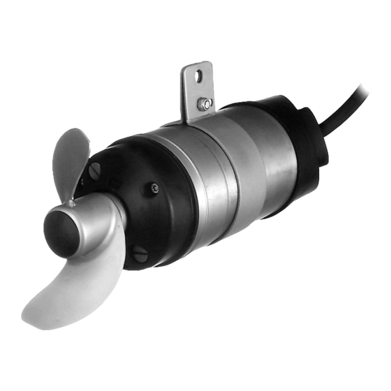
- Page 1 4610, 4620 edition 03 Workshop manual 4610, 4620 893542/03...
-
Page 2: Table Of Contents
4610, 4620 edition 03 PRODUCTS INCLUDED Specially approved Versiones (Ex) Standard versions 4610.490 EEx d llB T4 4610.410 4620.490 4620.410 4610.490 FM: Class l Div.1 Grp. C and D 4620.490 Class ll Div 1 Grp. E, F and G Class lll Div. 1 CONTENTS How to use the workshop manual ... -
Page 3: How To Use The Workshop Manual
4610, 4620 edition 03 HOW TO USE THE WORKSHOP MANUAL This workshop manual describes how to dismantle We would also like to point out that the practical work and assemble products 4610 and 4620 in connection involved in compiling this manual has been performed with repair and reconditioning work. -
Page 4: Data Plate Interpretation
4610, 4620 edition 03 DATA PLATE INTERPRETATION General data plate Serial number Product code + Number Curve code / Propeller code Country of origin Product number Additional information Phase; Type of current; Frequency Rated voltage Thermal protection Thermal class Rated shaft power International standard Degree of protection Rated current... -
Page 5: Approval Plate
4610, 4620 edition 03 DATA PLATE INTERPRETATION Approval plates Always together with the general data plate. European Norm, ATEX Directive EN 50 014, EN 50 018, EN 1127-1, ll 2 G EEx dll T4 Approval Approval authority + Approval Number Approval for Class I, Approved drive unit Stall time... -
Page 6: Technical Data
4610, 4620 edition 03 TECHNICAL DATA For weight, amperages, voltages, power ratings and Winding resistances at 20°C (68°F) speed, please refer to the data plate of the machine. 50 Hz 60 Hz Stator No Resistance Ohm/Phase Lubricants 640 67 01 12.6 15.4 Part No... -
Page 7: Specially Approved Mixer (Ex)
4610, 4620 edition 03 SPECIALLY APPROVED MIXER This chapter describes the specially approved mixer Guidelines for repair versions 4610.490 and 4620.490. For identification, Dismantling see the mixer data plate and approval plate. When dismantling Ex approved products, care must be taken as damage to flameproof faces can easily Specially approved mixers may occur. -
Page 8: Measurement For Widths And Gaps
4610, 4620 edition 03 SPECIALLY APPROVED MIXER Also violent damage will possibly have occurred to the Care and experience is required when taking any of stator windings, stator leads and terminal boards or these measurements, as the tolerances are very fine. bushings. -
Page 9: Dismantling
4610, 4620 edition 03 DISMANTLING / ASSEMBLY Dismantling Tools Screwdrivers Before starting Hexagon socket wrench 13 mm Hexagon socket head cup wrench 5 mm 6 mm WARNING! Torque wrench (7 - 17 Nm/5.2 - 12.6 ft/lb) Before starting work on the machine, hexagon socket head cup make sure that the machine is 6 mm... -
Page 10: Oil Draining
4610, 4620 edition 03 Remove the propeller. a. Remove the plastic plug (94). Tool: screwdriver b. Undo the central screw and washer. Tool: hex. socket head cup wrench (6 mm) c. Lift off the propeller together with screw and washer. Cut hazard A worn propeller may have sharp edges... -
Page 11: Plug-In Seal
4610, 4620 edition 03 Dismantle the oil housing (63). a Attach the mixer to the screw vice. b. Undo and remove the screws (and seal washers). Tool: hex. socket head cup wrench (5 mm). c. Fit M12 x 60 screws to the oil filling holes. d. - Page 12 4610, 4620 edition 03 Remove the spring (55). a. Knock gently on the bearing casing. Tool: club b. Remove the spring carefully with two screw drivers. Tool: screwdriver Dismantle the entrance flange (121). a. Turn the mixer in the screw vice (cable entry facing upwards).
-
Page 13: Cable Disconnection
4610, 4620 edition 03 Dismantle the connection housing (123). a. Remove the O-ring (29) by the cable. b. Undo and remove the screws. Tool: hex. socket head cup wrench (5 mm). c. Lift off and move the connection housing by the cable. - Page 14 4610, 4620 edition 03 Dismantle the shaft-rotor unit (60). a. Fit the screw to the back end of the stator housing unit (the bearing casing). Tool: screw M8 x 50 b. Press out the shaft-rotor unit by tighten the screw while holding the shaft-rotor unit with the other hand.
-
Page 15: Bearing Casing, Bearings
4610, 4620 edition 03 Dismantle the bearing casing (62) from the shaft- rotor unit (60). a. Fit the puller. Tool: puller 841362 NOTE! Only a puller with three claws must be used. Otherwise the bearing casing may be damaged. b. Attach the shaft-rotor unit to the screw vice. Use the puller as bracket. -
Page 16: Assembling
4610, 4620 edition 03 Assembling Before starting the work: Clean all parts throughly, particularly O-ring grooves. Assemble the bearing (51) and the bearing casing (62). a. Place the bearing casing on the work bench. b. Fit the bearing in position with the bearing designation upwards. - Page 17 4610, 4620 edition 03 Assemble the back bearing (50) to the shaft-rotor unit. a. Attach a tube to the screw vice. Tool: Tube D =24 mm b. Place the front shaft end into the tube. c. Fit a new bearing to the back shaft end. d.
-
Page 18: Plug-In Seal
4610, 4620 edition 03 Fit the spring (55). a. Fit the spring to the groove in the stator housing. Using a screwdriver will facilitate the mounting. Tool: screwdriver b. Pull the shaft-rotor unit against the spring. Shaft-rotor unit Stator housing Spring Fit the bearing cover (64). - Page 19 4610, 4620 edition 03 Fit the retaining ring. NOTE! The retaining ring has one flat and one crowned side. The crowned side should face the seal. a. Make sure that the retaining ring has entered the groove (check by knocking with a screw driver on the ring).
-
Page 20: Cable Connection (Wire Diagrams)
4610, 4620 edition 03 Connect the cable to the mixer. a. Thread following parts in order on to the cable: entrance flange (121) with O-ring (26) , gasket (113), washer (114), seal sleeve (111), washer (114), entrance cover (124) with O-ring (29) , connection housing (123). - Page 21 4610, 4620 edition 03 Connect the stator leads and cable leads 3 phase 6 lead stator, Y a. Connect the leads with closed end splices according to the wire diagram. All electrical equipment must be earthed (grounded). This concerns the machine as well as any control or monitoring equipment.
- Page 22 4610, 4620 edition 03 Fit connection housing (123). a. Attach the connection house to the mixer. The cable should be streched. b. Fit the screws and tighten to 7 Nm/5.2 ft lb . Tool: hex. socket head cup wrench (5mm) c.
-
Page 23: Propeller
4610, 4620 edition 03 Oil filling. a. Fit inspection screw (with O-ring). b.Fill up with new oil (0.15 lit/0.16 qt) in one of the oil holes. Tool: funnel Part No Denomination 90 17 52 Oil (Mobil Whiterex 309) 90 18 00 Oil (Castrol iloform BWN 205) c. -
Page 24: Notes
4610, 4620 edition 03 NOTES ........................................................................................................................................................................................................................................................................................................................................................................................................................................................................................................................................................................................................................................................................................................................................................................................................................................................................................................................................................................................................ -
Page 25: Exploded View
4610, 4620 edition 03 EXPLODED VIEW Accessories... -
Page 26: Mixer
4610, 4620 edition 03 EXPLODED VIEW 4610 4620 61.2 61.1 61.3 61.4 O-RING KIT BASIC REPAIR KIT... - Page 28 4610, 4620 edition 03 www.flygt.com...
Need help?
Do you have a question about the FLYGT 4610 and is the answer not in the manual?
Questions and answers
How to take out the stator for rewinding ?
To remove the stator for rewinding ITT Industries part number 4610, follow these steps:
1. Place the stator housing unit on the workbench.
2. Remove the O-ring (61.2) from the stator housing:
- Use stiff wires to remove the O-ring from the groove.
- Turn the stator housing upside down to help release the O-ring.
3. Remove the O-rings from the bearing casing (62):
- Fit the propeller screw (8) to the shaft end to protect it.
- Remove the O-rings.
4. Dismantle the bearing casing (62) from the shaft-rotor unit (60):
- Use a puller with three claws (Tool: puller 841362).
- Attach the shaft-rotor unit to a screw vice and use the puller as a bracket.
- Tighten the puller screw while holding the shaft-rotor unit.
- Remove the puller.
5. Dismantle the bearing (50) from the rotor-shaft:
- Attach a tube to the screw vice (Tool: tube for shaft).
- Place the shaft-rotor into the tube.
- Fit the puller to remove the bearing.
After dismantling, perform inspection and testing before rewinding the stator.
This answer is automatically generated