Advertisement
Quick Links
Quad 606 MK I and II DIY upgrade illustrated guidelines version 1.41
These are the illustrated step-by-step guidelines for upgrading your Quad 606
MK I or 606 MK II with the Dada Electronics upgrade-kit. This kit can also be
used for the 707and 909, the 707 and 909 is basically a 606 MKII with the
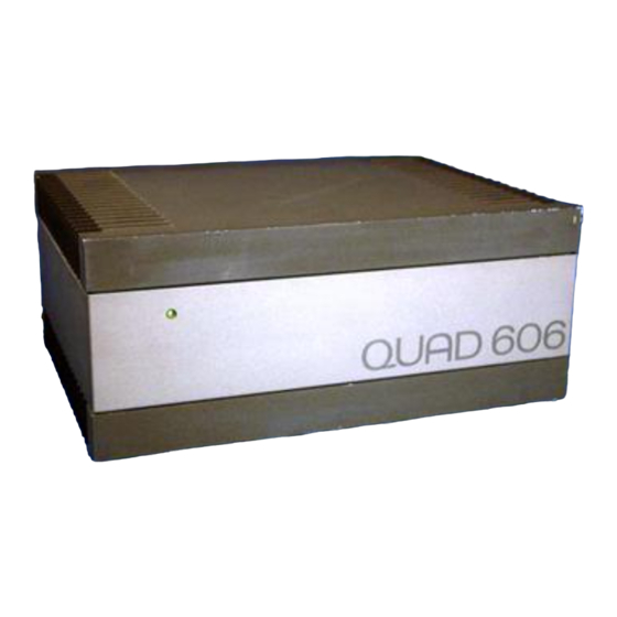
extra Quad Bus input circuit. The 606 MKI has a square casing; the 606 MKII
has beveled edges like the 707 and 909.
This kit is based on the highly successful one we developed for the 306 range
of amplifiers.
We will replace all electrolytic capacitors on the amplifier modules, input
connectors, some resistors and capacitors in the input- and feedback circuit
like Quad did in the 909. Low quality capacitors are replaced by Silvered-mica
capacitors. All the cabling will be replaced by Hi Q cabling in the original
colors.
We will also adapt the input-sensitivity (as an option) by increasing the local
feedback in the input-circuit. This further increases the signal-to-noise ratio
and makes the amplifier better adapted to modern sources.
We strongly advise to replace the power supply capacitors, but these are
depending on the type of 606.
Replacing the output transistors and drivers is an extra option; it will increase
the output peak current at difficult loads.
In some 606 amplifiers there is a mechanical hum. This is generated by the
transformer. Although Quad tried to solve this with a special suspension kit,
there is only one solution, replacing the transformer with a toroidal, like Quad
did in the 606 MKII, 707 and 909. We can do this kind of work, but only in one
of our shops.
Advertisement

Related Manuals for QUAD 606 MK I DIY


Summary of Contents for QUAD 606 MK I DIY
- Page 1 MK I or 606 MK II with the Dada Electronics upgrade-kit. This kit can also be used for the 707and 909, the 707 and 909 is basically a 606 MKII with the extra Quad Bus input circuit. The 606 MKI has a square casing; the 606 MKII has beveled edges like the 707 and 909.
- Page 2 We will do our best to answer within 24 hours 7/7. When the project is a success you will be listening to one of the best high-end, high-powered, current-dumping amplifiers ever made with a better- than-original Quad-sound. For indentifying your 606 and additional information, download the service manual.
- Page 3 Step 1 – The tools & the Components The tools you need: • A good quality soldering iron with a fine point (max 30) Watt or a soldering-station. • A desoldering-pump • A micro cutting nipper, a wire-stripper and a miniature pliers •...
- Page 4 BHC Aerovox 15.000µF 63V capacitor for the 606-II power-supply • Velleman K4701 Loudspeaker DC-protection unit, (two needed) • Dada Electronics DC-protection / delay, mono, the best! (two needed) • all other 606-components are also available See also the Quad Spot weblog.
- Page 5 Step 2 – Dismantling the 606 • Remove the bottom-cover (Philips n°2, 8 screws including 4 feet, also two screws on the back Philips n° 1), see exploded view in the appendix • Remove the wires from the 2 driver-boards (6 connectors/wires per board) •...
- Page 6 Step 4 - Upgrading the circuit boards. If you have a stabilized power-supply (+ 57 and – 54 Volt), a function- generator and a scope you might test the boards before upgrading them. If you don’t, no problem, you can upgrade the boards without them. When you connect a dual power supply to the board (+ and –...
- Page 7 If you want an input-sensitivity of 0 dBm (0.775 mV), 1mWatt in 600 ohms, which is standard, replace R11 with 12 Ohm. If you leave R11 in place the input-sensitivity will be 0.5 Volt. Step 5 – Replacing the output transistors (optional) Remove the output transistors and the driver transistors.
- Page 8 Step 6 - Testing the circuit boards When both boards are upgraded we'll connect them to a sinus-generator and to the scope. We'll connect + and - 50 Volt with our lab power-supply and connect a true-RMS multimeter to check the input- and output voltages. Following measurements are OK: - 0.01 Volt (max) DC on the outputs - 32 ..
- Page 9 Warning If the polarity of the caps is wrong they will explode! It is better to twist all cables that have to be soldered to the same point together before tinning them, it makes soldering a lot easier. Foresee cables to the boards as well.
- Page 10 The 606 MKII, also very useful information for the 707 and 909. Remove the 8 screws on the bottom and the 4 screws from the rear panel. Remove the bottom and the U shaped chassis part. The unit will looks like this. Remove the amplifier boards with a long Philips (posidriv) screwdriver;...
- Page 11 Remove the led circuit board from the front of the amplifier Remove the connectors from the PSU, make notes, or pictures! There is no need for soldering here. There are four large posidriv screws around the transformer, remove those. Be careful, sometimes they are a little bit covered by the transfo, lift the Psu Pcb to loosen those screws.
Need help?
Do you have a question about the 606 MK I DIY and is the answer not in the manual?
Questions and answers