Advertisement
Quick Links
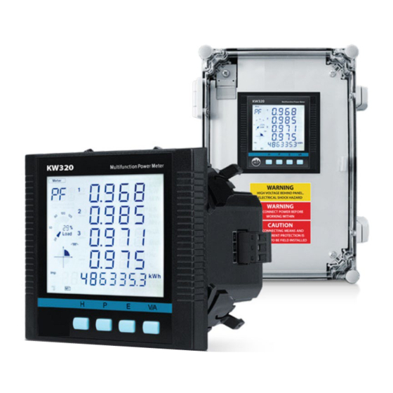
#N2-KW320 and N2-KW320Q Series– 8/14/23
Overview
4 Channel Power Meter, 0.1 Class, Multiple Communication
Protocols
The KW320 meter combines high performance with ease of
integration to provide a power and energy monitoring solution with
400 metering parameters. The KW320 series multifunction digital
power meter is designed using modern MCU and DSP technology
and its tamper-proof design is approved for revenue applications. It
integrates three-phase energy measuring and displaying, energy
accumulating, power quality analysis, malfunction alarming, data
logging and network communication. The meter measures
bidirectional, four quadrants kWh and kvarh. It provides
maximum/minimum records for power usage and power demand
parameters. All power and energy parameters can be viewed
remotely via Accuview Utility Software to monitor various
parameters. The meter comes standard to be mounted in a 4"
Round or an IEC 92mm DIN Square form or has the flexibility to be
mounted to 35mm DIN rail with the N2-AXM-DIN adapter (See
Accessories Ordering).
In addition, the KW320 also has an optional upgrade that includes a
NEMA 4X panel enclosure, pre-wired and labeled terminal for CT's,
terminal blocks for voltage input, and industrial grade fuses. The N2-KW320-P1-D-W-PC-C optional upgrade is an all-in-one Plug
n' play Pre-Wired Panel Enclosure that provides a perfect solution for retrofit projects where metering space is not pre-designed
in an electrical distribution panel. The meter supports user selectable RS-485 serial Modbus-RTU, BACnet™ MS/TP, multiple
Ethernet communication protocols, and Wi-Fi connection allows seamless integration with data acquisition systems. This product
provides demand measurement of Current, Active Power, Reactive Power and Apparent Power – see table 1 for all parameters
monitored and metered. It also provides demand forecasting as well as the peak demand. The KW320 series meter can record
the time and event regarding important parameter events such as the run time of the meter and alarm functions. The KW320
meter will accept both 333mV and Rogowski coil CT inputs (Input Field Selectable). Meters come standard with a four channel CT
input to accurately measure neutral current. CTs are sold separately as shown on the Split-Core, Solid-Core and Rogowski
Current Transformer product data sheets.
Applications: Tenant Billing, Data Centers, Sub-Metering Electrical Panel, Equipment Load Monitoring, Industrial Applications,
Predicted Maintenance, Renewable Energy, Overhead Cost Reduction, "NET ZERO" Buildings, LEED Buildings, Green Buildings,
and Refrigeration
The KW320 Power Meters are covered by a Five (5) Year Limited Warranty
Part Numbers
N2-KW320-P1-D-W-XX-C
N2-KW320Q-P1-D-W-PC-C
N2-AXM-DIN
Catalog No. 11-808-974-01
N2-KW320-P1-D-W-PC-C
N2-USB-RS485
Specifications subject to change without notice.
4-Channel Power Meters
N2-KW320Q-P1-D-W-XX-C
N2-AK-03
Specification
Page 1 of 20
Advertisement

Subscribe to Our Youtube Channel
Related Manuals for Carrier KW320


Summary of Contents for Carrier KW320
- Page 1 It also provides demand forecasting as well as the peak demand. The KW320 series meter can record the time and event regarding important parameter events such as the run time of the meter and alarm functions. The KW320 meter will accept both 333mV and Rogowski coil CT inputs (Input Field Selectable).
-
Page 2: Product Specifications
4-Channel Power Meters Specification #N2-KW320 and N2-KW320Q Series– 8/14/23 Product Specifications Service Type: Single Phase, 3 Phase – Four Wire (WYE), Three Phase – Three Wire (Delta) Power 1 : 100 - 415VAC, 50/60Hz, 100 - 300VDC on terminals L and N... - Page 3 4-Channel Power Meters Specification #N2-KW320 and N2-KW320Q Series– 8/14/23 Range: Wiring Connections: Screw Connections 14-22 AWG (2.5 to 0.34 mm 2 ) Wire Size: Mounting: ANSI C39.1 (4" Round) or an IEC 92mm DIN (Square) form. AcuView Utility Software, Windows Based; (USB-RS485 converter is required to...
- Page 4 4-Channel Power Meters Specification #N2-KW320 and N2-KW320Q Series– 8/14/23 Table #1 CATEGORY ITEM Parameters Phase Voltage V1, V2, V3, Vlnavg Line Voltage V12, V23, V31, Vllavg Current I1, I2, I3, In, Iavg Power P1, P2, P3, Psum Reactive Power Q1, Q2, Q3, Qsum...
- Page 5 4-Channel Power Meters Specification #N2-KW320 and N2-KW320Q Series– 8/14/23 Table #2 METERING Parameters Accuracy Resolution Range Voltage 0.1% 0.1V 10V~1000kV Current 0.1% 0.001A 5mA~50000A Power 0.1% -9999MW~9999MW Reactive Power 0.1% 1var -9999Mvar~9999Mvar Apparent Power 0.1% 0~9999MVA Power Demand 0.1% -9999MW~9999MW Reactive Power Demand 0.1%...
-
Page 6: Product Drawings
4-Channel Power Meters Specification #N2-KW320 and N2-KW320Q Series– 8/14/23 Product Drawings Power Meter Panel Upgrade Standard Ordering mV CT Rogowski Coil Panel Waveform Part # Meter Only Input Input Upgrade Capture N2-KW320-P1-D-W-X-C N2-KW320-P1-D-W-PC-C N2-KW320Q-P1-D-W-XX-C N2-KW320Q-P1-D-W-PC-C Specifications subject to change without notice. - Page 7 4-Channel Power Meters Specification #N2-KW320 and N2-KW320Q Series– 8/14/23 Accessories Ordering Part # Description N2-AXM-DIN KW320 DIN Rail Adapter N2-USB-RS485 RS485 to USB Converter N2-AK-03 Three Fuse Pack; Inline Fuse Kit; 600V, 2A; Slow Blow Specifications subject to change without notice.
-
Page 8: Mounting Instructions
Visible portion (for display and control) after mounting onto a panel 3. Key Four keys are used to select display and set The KW320 series meter enclosure is made of high strength anti-combustible 4. Enclosure engineering plastic 5. Voltage Input Terminals Used for voltage input Specifications subject to change without notice. - Page 9 Operation: -25 to 70°C (-13 to 158°F) Storage: -40 to 85°C (-40 to 185°F) Humidity: 5% to 95% non-condensing. Location: KW320 series meter should be installed in a dry and dust free environment. Avoid exposing the meter to excessive heat, radiation and high electrical noise sources. Installation Steps: The KW320 series meter can be installed into a standard ANSI C39.1 (4"...
-
Page 10: Wiring Instructions
4-Channel Power Meters Installation and Operation #N2-KW320 and N2-KW320Q Series– 8/14/23 3. Install clips on the back side of the meter and secure tightly to ensure the meter is affixed to the panel. NOTE The display meter and the remote display unit have the same installation method. The DIN rail meter is simply installed on a 35mm DIN rail. - Page 11 Terminal Strips There are four terminal strips at the back of the KW320 series meter. The three-phase voltage and current are represented by using 1, 2 and 3 respectively. These numbers have the same meaning as A, B and C or R, S and T used in other literature.
- Page 12 Voltage Input Maximum input voltage for the KW320 series meter shall not exceed 400LN/690LL VAC rms for three phase or 400LN VAC rms for single phase. Potential Transformer (PT) must be used for high voltage systems. Typical secondary output for PT's shall be 100V or 120V.
- Page 13 VN Connection VN is the reference point of the KW320 series meter voltage input. Low wire resistance helps improve the measurement accuracy. Different system wiring 20 modes require different VN connection methods. Please refer to the wiring diagram section for more details.
- Page 14 4-Channel Power Meters Installation and Operation #N2-KW320 and N2-KW320Q Series– 8/14/23 Figure 2: 9b3LN with 3PT 3-Phase 3-Line Direct Connection Mode (3LL): In a 3-Phase 3-Line system, power line A, B and C are connected to V1, V2 and V3 directly. VN is floated. The voltage input mode of the meter should be set to 3LL.
- Page 15 4-Channel Power Meters Installation and Operation #N2-KW320 and N2-KW320Q Series– 8/14/23 3-Phase 3-Line Open Delta Mode (2LL): Open Delta Wiring Mode is often used in high voltage systems. V2 and VN are connected together in this mode. The voltage input mode of the meter should be set to 2LL for this voltage input wiring mode.
- Page 16 4-Channel Power Meters Installation and Operation #N2-KW320 and N2-KW320Q Series– 8/14/23 2CT: Figure 6: 2CT's 1CT: Figure 7: 1CT Specifications subject to change without notice. Catalog No. 11-808-974-01 Page 16 of 20...
- Page 17 4-Channel Power Meters Installation and Operation #N2-KW320 and N2-KW320Q Series– 8/14/23 Frequently Used Wiring Method In this section, the most common voltage and current wiring combinations are shown in different diagrams. In order to display measurement readings correctly, please select the appropriate wiring diagram according to your setup and application.
- Page 18 4-Channel Power Meters Installation and Operation #N2-KW320 and N2-KW320Q Series– 8/14/23 Figure 9: 2LL, 3CT Figure 10: 1LN, 1CT Specifications subject to change without notice. Catalog No. 11-808-974-01 Page 18 of 20...
- Page 19 (0.5mm2) or higher. The overall length of the RS485 cable connecting all devices should not exceed 1200m (40000 ft). The KW320 series meter is used as a slave device of masters such as a PC, PLC, Data Collector or RTU.
- Page 20 4-Channel Power Meters Installation and Operation #N2-KW320 and N2-KW320Q Series– 8/14/23 Appendix – Symbols Key Potential for death, serious injury, or permanent damage to a system. Warning Potential for injury, damage to a system, or system failure. Caution Useful information not related to injury or system damage.
Need help?
Do you have a question about the KW320 and is the answer not in the manual?
Questions and answers