Table of Contents
Advertisement
Quick Links
Advertisement
Table of Contents

Related Manuals for DOD Technologies ChemLogic CL96

Summary of Contents for DOD Technologies ChemLogic CL96
- Page 1 ChemLogic CL96 ® 96-Point Continuous Gas Detector Operating Manual...
- Page 2 ChemLogic® CL96 Operating Manual DOD Technologies, Inc. 675 Industrial Drive Bldg. A. Cary, IL 60013 solutions@dodtec.com Phone 815.788.5200 • Fax 815.788.5300 DODtec.com DODtec.com DC-TEC-MAN-CL96_B REV 1/9/2024 815-788-5200 Page 2 solutions@dodtec.com...
-
Page 3: Table Of Contents
ChemLogic® CL96 Operating Manual Table of Contents Chapter 1 – Overview ..................................7 Introduction ..................................7 1.2 Theory of Operation ................................7 1.3 Sampling and Monitoring ..............................8 1.3.1 Flow Connections ................................8 1.4 Electrical Connections ................................8 Chapter 2 – Features ..................................9 2.1 External Layout &... - Page 4 ChemLogic® CL96 Operating Manual 4.5 Concentration Logging ............................... 17 4.6 Install New Tape.................................. 18 4.7 USB Storage..................................18 4.8 Setup Complete ................................... 18 Chapter 5 General Machine Operation ............................19 5.1 Introduction ..................................19 5.2 General Screen Navigation ..............................19 5.3 Initialization ..................................
- Page 5 ChemLogic® CL96 Operating Manual Idle Timeout ....................................43 Output Contact ..................................43 Flow Fault Filter ..................................43 6.2.e Setup -> Date Time ................................44 6.2.f Setup-> Passwords ................................44 6.3 Factory Setup Sub-Menu ..............................45 6.3.a Setup -> Factory -> System .............................. 46 6.3.b Setup ->...
- Page 6 ChemLogic® CL96 Operating Manual CL96 System Specification ............................... 69 Appendix D – System Event Message ............................70 Appendix E – LDL List .................................. 71 Appendix F – Hard Wire Connection (Optional) ......................... 74 Appendix G – Optional Secondary Enclosures ........................... 75 G.1 Mounting A Secondary Enclosure .............................
-
Page 7: Chapter 1 - Overview
The CL96 can monitor and detect a wide range of gases. It is designed for continuous and prolonged operation when routine maintenance is performed (per factory specifications). The CL96 employs DOD Technologies’ ChemLogic colorimetric technology, utilizing ChemLogic cassettes with chemically infused tape for fast and accurate gas detection. -
Page 8: Sampling And Monitoring
ChemLogic® CL96 Operating Manual 1.3 Sampling and Monitoring The system draws sample flow simultaneously from all installed points. Part of the sample flow is diverted across the ChemLogic tape where it is analyzed. Each 16-point analyzer exhausts through a single port. 1.3.1 Flow Connections Flow connections consist of “quick-connect”... -
Page 9: Chapter 2 - Features
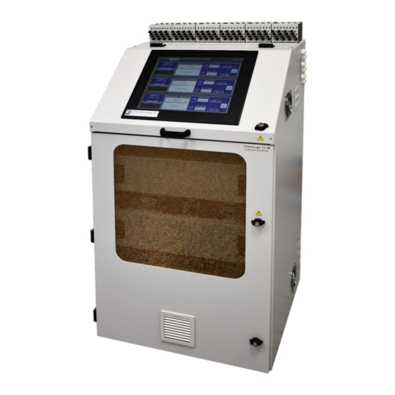
ChemLogic® CL96 Operating Manual Chapter 2 – Features 2.1 External Layout & Dimensions Flow Adjustment & Sample tubing ports Wiring Knockouts Touch Screen – 19” Keyed Door Access A/C Power Switch DODtec.com DC-TEC-MAN-CL96_B REV 1/9/2024 815-788-5200 Page 9 solutions@dodtec.com... -
Page 10: Status Lamp (Optional)
ChemLogic® CL96 Operating Manual 2.1.1 Status Lamp (OPTIONAL) The optional status lamp consists of 4 colored lights – Red, Orange, Blue, and Green along with an audible alarm. See Appendix A for ordering information. 2.1.2 Output Wiring Knockouts Knockouts for output wiring are located on the right-side panel near the top. 2.1.3 Touch Screen Display The CL96 uses a full color 19-inch touch panel LCD display. -
Page 11: Take-Up Reel
ChemLogic® CL96 Operating Manual 2.1.9 Take-up Reel Empty take-up reels are inserted at the time of ChemLogic tape installation (see section 6.3). During installation, the previous take-up reel which is full is removed from CL96 and discarded. The previous ChemLogic tape reel which is now empty should then be used as the next take-up reel. 2.1.10 Tubing Connections Sample tubing and exhaust use a quick connection system for simple installation. -
Page 12: Internal Layout - Service Area
ChemLogic® CL96 Operating Manual 2.3 Internal Layout – Service Area Internal access to the CL96 for installation and service uses the keyed handle located on the right side of the front panel. Figure 2.3 shows the internal layout of the CL96 with the service door open. The door should be opened by trained service personnel (See section 6.2 ) Figure 2.3 WARNING: Electric shock possible. -
Page 13: Usb Storage
If you forget or lose your password, please contact DOD Technologies, Inc. You can change the passwords on the menu in the “Setup” area – see chapter 6. See Chapter 8 for contact information. -
Page 14: Chapter 3 - Installation
ChemLogic® CL96 Operating Manual Chapter 3 – Installation WARNING: Electric shock possible. Turn off the unit and disconnect A/C power to the unit before servicing. WARNING: If the CL96 is used in a manner not specified by the manufacturer, the protection provided by the equipment may become impaired. -
Page 15: Sample Tubing
Sample tubing is connected to the CL96 on the top the unit. All sample tubes are 1/4” OD x 3/16” ID Teflon FEP (400 ft max length) which may be purchased from DOD Technologies, INC (See Appendix A). Fully IMPORTANT : All sample tubing used with the CL96 must be ¼”... -
Page 16: Output Wiring
ChemLogic® CL96 Operating Manual 3.6 Output Wiring See Appendix B for a listing of various output module connections available on the CL96. 3.6.1 Standard Output Wiring The standard output modules included with the system require an external 24V supply connected to the CL96 to supply power for the outputs. -
Page 17: Chapter 4 - Setup & Configuration
ChemLogic® CL96 Operating Manual Chapter 4 – Setup & Configuration 4.1 Set System Date and Time See section 6.2.e 4.2 Gas Selection Each point on the CL96 must be setup for the appropriate gas and configured accordingly. See section 6.2.a for information on selecting the gas for each point. -
Page 18: Install New Tape
The use of USB Storage drive is required to retain historical and performance of information including events, alarms, and gas concentrations. High reliability USB Storage drives are available from DOD technologies (see Appendix A) and at most retail electronic stores. See section 7.5 for information on inserting and replacing a USB drive. -
Page 19: Chapter 5 General Machine Operation
ChemLogic® CL96 Operating Manual Chapter 5 General Machine Operation 5.1 Introduction The touch screen on the CL96 is used for all configuration and control of the unit. Analysis mode is active by default approximately 2 minutes after power on unless an operator intervenes. The machine is designed to continually monitor for gas 24/7. - Page 20 ChemLogic® CL96 Operating Manual Not installed Idle (Not analyzing) Analysis Active Maintenance Fault Critical fault Gas Alarm Table 5.2 Table 5.2 lists the colors in priority from lowest to highest since only 1 color will be displayed at a time. •...
-
Page 21: Initialization
ChemLogic® CL96 Operating Manual 5.3 Initialization When the CL96 is powered on it will begin with an initialization screen which is followed by the automatic restart screen (figure 5.3) Figure 5.3 If the operator touched another menu button before the timer reaches 0 the machine will go to that screen and WILL NOT enter analysis (unless of course the operator touched the analysis button). -
Page 22: Chapter 6 The Main Menu
ChemLogic® CL96 Operating Manual Chapter 6 The Main Menu 6.1 Main Menu The main menu allows the operator to start/stop analysis and access to all information available while remaining in Analysis. 6.1.a Analysis As the name implies, touching the ‘Analysis’ button will start the CL96 analysis for all active points. (see Setup in section 6.2.a). - Page 23 ChemLogic® CL96 Operating Manual Figure 6.1.a.1 The color of each point on the analysis screen will change according to the current state of the point: Disabled, Idle, Analyzing, Maintenance fault, or Alarm. (see colors in table 5.2) Ex: Figure 6.1.a.2 displays which point 9 on analyzer A would look like when a full-scale reading is found while monitoring for H2SE(0-500ppb).
-
Page 24: Point Trend Detail
ChemLogic® CL96 Operating Manual 6.1.a.2 Point Trend Detail Touching the gray area on any *active point on the analysis screen will display the detailed information for the selected point as shown in figure 6.1.a.3. The screen details the point #, name, location, range, alarm levels, flow level, current concentration, and a graph of the previous 15 minutes of concentration detected. -
Page 25: Load Tape
ChemLogic® CL96 Operating Manual 6.1.b Load Tape Touching the ‘Load Tape’ button on the main menu will bring up the screen shown below. Note that stacked analyzers can only be operated together although each analyzer tray can be started and stopped independently. -
Page 26: Faults/Events
ChemLogic® CL96 Operating Manual 6.1.c Faults/Events Touching the Faults/Events buttons on the main menu will bring up the screen show in figure 6.1.c. Note this important difference between this screen and the fault/events screen on the ‘History’ sub-menu. The faults/events on the main menu shown on figure 6.1.c retains a list of the most recent events (128-256). Regardless of whether a USB drive is inserted this list will show the most recent events. -
Page 27: History
ChemLogic® CL96 Operating Manual 6.1.d History Touching the History button on the main menu will bring up the sub-menu screen shown in figure 6.6. This sub- menu gives access to the historical data stored on the USB flash drive. IMPORTANT : The CL96 stores all historical data to the USB drive. -
Page 28: History -> Faults/Events
ChemLogic® CL96 Operating Manual 6.1.d.2 History -> Faults/Events Touching the Faults/Events button on the History sub-menu will bring up screen show below. This screen shows only the events that occurred on the specific date selected using the calendar. Figure 6.1.d.2 Touch the ‘Fault/Alarm Reset’... -
Page 29: History -> Twa
ChemLogic® CL96 Operating Manual 6.1.d.3 History -> TWA Touching the TWA button on the main menu will bring up the sub-menu screen shown below. The operator may use the calendar to select the TWA information for each date. Figure 6.1.d.3 DODtec.com DC-TEC-MAN-CL96_B REV 1/9/2024... -
Page 30: History -> Storage
ChemLogic® CL96 Operating Manual 6.1.d.4 History -> Storage 6.1.d.5 History -> Transfer DODtec.com DC-TEC-MAN-CL96_B REV 1/9/2024 815-788-5200 Page 30 solutions@dodtec.com... -
Page 31: Help
An interactive CL96 User Manual is available in this section. It is menu-driven to help you quickly find specifications and other useful information on your ChemLogic CL96 system. A PDF copy of the User Manual can also be viewed or downloaded by visiting the CL96 product page at DODtec.com. -
Page 32: Help -> Diagrams
ChemLogic® CL96 Operating Manual 6.1.e.2 Help -> Diagrams 6.1.e.3 Help -> Contact DOD DODtec.com DC-TEC-MAN-CL96_B REV 1/9/2024 815-788-5200 Page 32 solutions@dodtec.com... -
Page 33: Help -> Configuration
ChemLogic® CL96 Operating Manual 6.1.e.4 Help -> Configuration DODtec.com DC-TEC-MAN-CL96_B REV 1/9/2024 815-788-5200 Page 33 solutions@dodtec.com... -
Page 34: Help -> About
ChemLogic® CL96 Operating Manual 6.1.e.5 Help -> About Selecting the ‘About’ tab from the ‘Help’ menu displays the screen shown below. This screen contains important system details including the version, license number, serial number and more. Note: Certain references in the photo above have been altered or omitted for proprietary purposes. Details and references will vary by system. -
Page 35: Setup -> Point Setup
ChemLogic® CL96 Operating Manual 6.2.a Setup -> Point Setup When the Point Setup button is touched the screen below appears. The buttons along the top allow selection of each analyzer that is installed (if not installed the buttons are disabled). Selecting an analyzer with the button at the top will display the configuration of the corresponding 16 points for the selected analyzer. -
Page 36: Setup -Adjust Flow
ChemLogic® CL96 Operating Manual IMPORTANT : When a point is disabled no gas analysis is performed. Figure 6.2.a.2 6.2.b Setup -Adjust Flow When the Adjust Flow, button is touched the screen below appears. The buttons along the top allow selection of each analyzer that is installed (if not installed the buttons are disabled). - Page 37 ChemLogic® CL96 Operating Manual IMPORTANT : Although only 16 points can be adjusted at a time, both pumps for the analyzer tray are active at the same time (if 32 points are installed). Figure 6.2.b NOTE : There may be a slight delay between the time the control valve is turned and the update reading the CL96.
-
Page 38: C Setup -> Outputs
ChemLogic® CL96 Operating Manual 6.2.C Setup -> Outputs When the Point Setup button is touched the Outputs, Sub-Menu appears as described below. The outputs screen allows calibration & viewing of all output modules installed on the CL96. 6.2.c.1 Setup -> Outputs -> Alarms When the Test Faults button is touched the screen below is displayed. -
Page 39: Setup -> Outputs -> Point Alarms
ChemLogic® CL96 Operating Manual 6.2.c.2 Setup -> Outputs -> Point Alarms When the Test Points button is touched the screen below is displayed. The buttons along the top allow selections of each analyzer that is installed (if not installed the button are disabled). The same screen is used to test the 24V output modules and/or the relay contacts if installed. -
Page 40: Setup -> Outputs -> 4-20Ma
ChemLogic® CL96 Operating Manual 6.2.c.3 Setup -> Outputs -> 4-20mA 6.2.c.4 Setup -> Outputs -> Comm Data DODtec.com DC-TEC-MAN-CL96_B REV 1/9/2024 815-788-5200 Page 40 solutions@dodtec.com... -
Page 41: Setup -> Outputs -> Optic Test
ChemLogic® CL96 Operating Manual 6.2.c.5 Setup -> Outputs -> Optic Test DODtec.com DC-TEC-MAN-CL96_B REV 1/9/2024 815-788-5200 Page 41 solutions@dodtec.com... -
Page 42: Setup -> Configure
ChemLogic® CL96 Operating Manual 6.2.d Setup -> Configure When the Configure button is touched the screen below is displayed. Each of the blocks on the screen are described below. Figure 6.2.d Logging Configuration Three components make up the logging configuration of the system: Where to log, what to log, and how often to log. -
Page 43: Idle Timeout
ChemLogic® CL96 Operating Manual IMPORTANT : Hard Disk 1 and Hard Disk 2 are reserved for use by the CL96 system. Each USB drive installed in the USB Hub will be sequentially named beginning with Hard Disk 3. The drop-down list for Conc. Logging gives the operator the three available choices for what concentration data should be logged: 1. -
Page 44: Setup -> Date Time
ChemLogic® CL96 Operating Manual 6.2.e Setup -> Date Time When the Date/Time button is touched the below is displayed. After adjusting the correct date and time on the screen be sure to touch the ‘Set’ button to save the settings. Figure 6.2.e 6.2.f Setup->... -
Page 45: Factory Setup Sub-Menu
ChemLogic® CL96 Operating Manual 6.3 Factory Setup Sub-Menu The Factory setup sub-menu contains the configuration screen for the CL96 necessary for normal operation. Access to the Setup sub-menu is password protected (see section 6.2.f). DODtec.com DC-TEC-MAN-CL96_B REV 1/9/2024 815-788-5200 Page 45 solutions@dodtec.com... -
Page 46: Setup -> Factory -> System
ChemLogic® CL96 Operating Manual 6.3.a Setup -> Factory -> System DODtec.com DC-TEC-MAN-CL96_B REV 1/9/2024 815-788-5200 Page 46 solutions@dodtec.com... -
Page 47: Setup -> Factory -> Multi Pt
ChemLogic® CL96 Operating Manual 6.3.b Setup -> Factory -> Multi Pt DODtec.com DC-TEC-MAN-CL96_B REV 1/9/2024 815-788-5200 Page 47 solutions@dodtec.com... -
Page 48: Setup -> Factory -> Simulation
ChemLogic® CL96 Operating Manual 6.3.c Setup -> Factory -> Simulation DODtec.com DC-TEC-MAN-CL96_B REV 1/9/2024 815-788-5200 Page 48 solutions@dodtec.com... -
Page 49: Setup -> Factory -> Configuration
ChemLogic® CL96 Operating Manual 6.3.d Setup -> Factory -> Configuration DODtec.com DC-TEC-MAN-CL96_B REV 1/9/2024 815-788-5200 Page 49 solutions@dodtec.com... -
Page 50: Setup -> Factory -> Settings
ChemLogic® CL96 Operating Manual 6.3.e Setup -> Factory -> Settings To access the Configuration Settings menu for the CL96, complete the following steps: 1. CL96 Main Menu SETUP 2. Enter password 3. SETUP Menu FACTORY Menu DODtec.com DC-TEC-MAN-CL96_B REV 1/9/2024 815-788-5200 Page 50 solutions@dodtec.com... -
Page 51: Minimum Visible Stain
ChemLogic® CL96 Operating Manual 4. From the FACTORY Menu SETTINGS 6.3.e.1 Minimum Visible Stain The Minimum Visible Stain (MVS) feature was implemented as an enhancement (in 2017) as part of the software version 17.0130 update. MVS allows color change or the stain to continue to accumulate during the same window, or on the same spot of the ChemLogic cassette, until the minimum count threshold is achieved. - Page 52 ChemLogic® CL96 Operating Manual The typical counts required to see a stain with the human eye is approximately 200 counts. This varies slightly by gas and ChemLogic cassette. The MVS software feature can be accessed and modified by following the below path. From the FACTORY Menu SETTINGS MVS was implemented to allow a stain or color change continue to accumulate to pre-set count changes.
-
Page 53: Dual Pump Option
ChemLogic® CL96 Operating Manual 6.3.e.2 Dual Pump Option The CL96 Continuous Gas Monitor has an optional dual pump feature. This option includes an additional pump for each 16-point analyzer, resulting in up to 80% reduced transport time. This dual pump feature also acts as a backup pump in the event of a pump failure. - Page 54 ChemLogic® CL96 Operating Manual 2. Dual pump transport times and flow rates – OPTIONAL CL96 CONFIGURATION Table 2 a. Dual Pump Option – 96-point system (6, 16 points analyzers) would include 12 pumps. Figure 1 b. Dual Pump Option – Back up feature included with dual pump option. Check valves connecting the two pumps and automatically closing the valve when one of the pumps fails.
- Page 55 ChemLogic® CL96 Operating Manual Figure 2 The Dual Pump option is only available when initially ordering the CL96. It is not available as a field upgrade. To ensure your system is properly equipped with this option, reference the following DOD part numbers: 2-800-071 Option –...
-
Page 56: Parallel Sampling
ChemLogic® CL96 Operating Manual 6.3.e.3 Parallel Sampling The CL96 Parallel Sampling option allows a sample line to be shared between 2 or 3 analyzers, allowing multiple gases to be analyzed from a single sample line. The main sample line requires ¼”OD x 3/16” ID FEP Teflon tubing connected by ¼”... -
Page 57: Parallel Sampling Transport Times
ChemLogic® CL96 Operating Manual 6.3.e.3.1 Parallel Sampling Transport Times The table below shows the time required for a sample to travel from the sampling location or the end of the sample line to the CL96. The transport times are based on various tubing lengths and sample lines. 6.3.e.4 Reference Validation Fault CL96 software version 16.0620 (2016), implemented three features to take action when a reference validation message occurs. -
Page 58: Setup -> Factory -> Restore
ChemLogic® CL96 Operating Manual a. When the reference validation occurs, a general fault is triggered and all points on the affected optic block are disabled (4 points) 3. REF FAULT DISABLE POINT a. When the reference validation occurs, a general fault is triggered and the single affected point is disabled (1 point) IMPORTANT : If only number 1 (REFERENCE FAULT CRITICAL) is enabled, it will remain... -
Page 59: Chapter 7 - Maintenance And Disposal
ChemLogic® CL96 Operating Manual Chapter 7 – Maintenance and Disposal DANGER: Disconnect power before servicing 7.1 Returning to a Safe State (Post-Service) Before returning the CL96 to service after maintenance or perform verify the following checks: Verify all A/C power connections are secured properly. •... -
Page 60: Chemlogic ® Cassette
ChemLogic® CL96 Operating Manual 7.4 ChemLogic Cassette ® The ChemLogic cassette paper tape has an expiration date printed on the label. Expired tape should be disposed of and replaced with new tape to assure proper gas concentration readings. Each DOD ChemLogic® tape cartridge for the CL96 will last for 120 days under normal usage. -
Page 61: End Of Line Particular Filters
ChemLogic® CL96 Operating Manual 7.6 End of line particular filters End of line (point detection particulate filters which protect the CL96 from damage are required on all points including points not being monitored. Table 7.1 details the type of filter required for each gas. Filters must be replaced on a regular basis as shown in the table. -
Page 62: Flow Adjustment
ChemLogic® CL96 Operating Manual 7.7 Flow Adjustment Each channel should be adjusted whenever a new ChemLogic® tape or particulate filter is installed. See section 6.2.b. 7.8 USB Storage Drive Replacement It is highly recommended to keep a USB flash drive inserted in the unit at all times. A general fault is issued anytime a USB drive is not inserted or full. -
Page 63: Chapter 8 - Service & Support
Cary, IL 60013 E-mail us at: solutions@dodtec.com Visit our website: DODtec.com For permanent discontinuation: Discontinued units may be eligible for recycling. Please contact DOD Technologies for additional information and instructions for arranging safe return of your equipment. DODtec.com DC-TEC-MAN-CL96_B REV 1/9/2024 815-788-5200 Page 63 solutions@dodtec.com... -
Page 64: Appendix A - Parts & Accessories
ChemLogic® CL96 Operating Manual Appendix A – Parts & Accessories Filters & Tubing PART PART DESCRIPTION NUMBER 780248 Particulate Filter for Non-Corrosives (Phosgene & Hydrides) 2-800-013 Particulate Filter for Corrosive Gases (Mineral Acids) 2-500-052 Pyrolyzer Freon Filter 2-100-503 Filter for H2S Scrubber 60009 Filter Housing for Teflon Membranes (Mineral Acids) 2-500-502... -
Page 65: Appendix B - I/O Connection Detail
EK1101 module. Two different power sources are used for the module. Power to operate the module itself is supplied by the CL96 power and prewired by DOD Technologies. – do NOT remove. Power for all outputs must be supplied by the customer on pins 6 and 7. -
Page 66: Standard Output Module (24 V Sinking)
ChemLogic® CL96 Operating Manual B.2 Standard Output Module (24 V Sinking) Figure B.2.1 Figure B.2.2 DODtec.com DC-TEC-MAN-CL96_B REV 1/9/2024 815-788-5200 Page 66 solutions@dodtec.com... -
Page 67: Optional Output Relays
ChemLogic® CL96 Operating Manual B.3 Optional Output Relays Figure B.3.1 Figure B.3.2 DODtec.com DC-TEC-MAN-CL96_B REV 1/9/2024 815-788-5200 Page 67 solutions@dodtec.com... -
Page 68: Optional 4-20 Outputs
ChemLogic® CL96 Operating Manual B.4 Optional 4-20 Outputs Figure B.4.1 Figure B.4.2 Figure B.4.3 Repeat for each module – Points 5-8, 9-12, etc. DODtec.com DC-TEC-MAN-CL96_B REV 1/9/2024 815-788-5200 Page 68 solutions@dodtec.com... -
Page 69: Appendix C - System Specifications
ChemLogic® CL96 Operating Manual Appendix C – System Specifications The CL96 is designed for safe use under the following conditions Indoor use only • Altitude up to 2,000 m • • Temperature 5ºC - 40 ºC Maximum relative humidity 80% for temperatures up to 31 ºC decreasing linearly to 50% relative •... -
Page 70: Appendix D - System Event Message
ChemLogic® CL96 Operating Manual Appendix D – System Event Message COLOR CODING Gas Alarm ORANGE Service Fault (critical) YELLOW Maintenance (non-critical) BLUE Information Message GREEN Status (during analysis) DODtec.com DC-TEC-MAN-CL96_B REV 1/9/2024 815-788-5200 Page 70 solutions@dodtec.com... -
Page 71: Appendix E - Ldl List
ChemLogic® CL96 Operating Manual Appendix E – LDL List ChemLogi Calibration Full Name Gas Family Units c Cassette Scale Ammonia Ammonia 2-800-405 1-700-050 Ammonia Ammonia 2-800-405 1-700-050 Arsenic Pentafluoride^ AsF5 (HF) MA-SG 2-800-409 1-420-150 AsHCl3 Arsenic Trichloride^^ (HCl) MA-SG 2-800-409 1-420-150 Arsenic Trifluoride^ AsF3 (HF) - Page 72 ChemLogic® CL96 Operating Manual ChemLogi Calibration Full Name Gas Family Units c Cassette Scale Chlorine- Fluorine (SG) 2-800-414 1,000 41.6 1-560-150 H2SiF6 Fluorosilicic acid^ (HF) MA-SG 2-800-409 1-420-150 Germane GeH4 Hydrides 2-800-401 2,000 62.1 1-300-050 Hydrides Germane GeH4 (LL) 2-800-406 2,000 62.1 1-300-050...
- Page 73 2-800-409 1-420-150 * Additional ranges may be available and are subject to change. Please see specific product brochure or contact DOD Technologies. ** Requires pyrolyzer option for detection ^ Compounds which hydrolyze to HF ^^ Compounds which hydrolyze to HCl...
-
Page 74: Appendix F - Hard Wire Connection (Optional)
ChemLogic® CL96 Operating Manual Appendix F – Hard Wire Connection (Optional) :The detachable power cord or the supply line wiring must meet the WARNING rating specified below . When the hard-wired option is specified the installation must be done by a qualified electrician. IMPORTANT: When installing A/C voltage to the CL96 for the hard wire connection read carefully: A switch or circuit-breaker shall be included in the building installation. -
Page 75: Appendix G - Optional Secondary Enclosures
ChemLogic® CL96 Operating Manual Appendix G – Optional Secondary Enclosures WARNING :Disconnect power before servicing. Many of the I/O options for the CL96 are packaged as secondary enclosures. These secondary enclosures are typically located remotely, mounted on the side or close to the CL96 cabinet. This section describes mounting (G.1), A/C Power (G.2), connecting to the CL96 (G.3), and external wiring (G.4) for the varying options available. -
Page 76: Connecting A/C Power To The Secondary Enclosure
ChemLogic® CL96 Operating Manual Remove the nut and lock washer from each of the four bolts, mount the external cabinets onto the four bolts using the attached bracket then replace the lock washers and nuts. Tighten the nuts to secure the cabinet to the side of the CL96 panel. -
Page 77: Installing The A/C Power Cable
ChemLogic® CL96 Operating Manual Figure G.2.2 G.2.2 Installing the A/C Power Cable Insert the exposed wires of the power cord through the hole in the fitting from the outside and then into • the cord grip cap as shown in figure G.2.3. Figure G.2.3 Pull the appropriate length of cord inside the cabinet to allow the shielded portion of the cable to reach •... -
Page 78: Connecting To The Cl96
ChemLogic® CL96 Operating Manual Attach the LineBlack wire to the Power Filter at the label for Screw #1, tighten securely. • Push the plastic cover back into place on the Power Filter over screws connections #1 and #2. • Locate the Protective Earth (PE) Grown stud as shown in figure G.2.4. •... -
Page 79: Wiring Output Modules
ChemLogic® CL96 Operating Manual Multiple external cabinets can be daisy-chained using the bottom RJ-45 connector as a starting point • for the second shielded cable. Figure G.3.1 G.4 Wiring Output Modules G.4.1 Analog (4-20 ma) Output Wiring See Appendix B.4 for information on wiring to analog output modules. G.4.2 Beckhoff Form A Relays See Appendix B.3 for information on wiring to Beckhoff Relay Modules. - Page 80 ChemLogic® CL96 Operating Manual Note: 32 point analyzers will have another 32 relays for points 17-32. Each of the relays has a normally open and a normally closed connection along with a common. Figure G.4.2 below shows the order of the relays as labeled inside the cabinet.
-
Page 81: Appendix H - Data Communication
H.1.1 Data Format The Ehternet/IP interface allows remote monitoring of fault/alarm outputs, concentration levels, and fault rest. You must supply the IP Address of the CL96 to DOD Technologies, INC to configure the Ethernet/IP. The data is mapped as: Downlink (From Master to CL96):... - Page 82 ChemLogic® CL96 Operating Manual Offset Data Description Format (Words) Words Connection Status Concentration levels for all 96 points Conc * 10 (eg. 23 = 2.3 actual conc) Analyzer A Alarm Level 1 Indicators Bit 0 - 15 = Alarm Level 1 points 1-16 Analyzer A Alarm Level 1 Indicators Bit 0 - 15 = Alarm Level 1 points 17-32 Analyzer B Alarm Level 1 Indicators...
-
Page 83: Profibus
ChemLogic® CL96 Operating Manual H.2 – Profibus The following information is available on the Profibus/Slave interface. The CL96 Faults/Alarms (Discrete Outputs) Description Type Token Machine Critical Fault Machine has critical fault Boolean Machine Maintenance Fault Machine has a maintenance issue Boolean Machine Gas Alarm 1 Level 1 Gas Alarm at Least 1 Machine Point... -
Page 84: Data Format
ChemLogic® CL96 Operating Manual H.2.1 Data Format Default Slave ID: 2 Size (Bytes): 228 Size # Byte # Data Description Format Bytes (Bytes) Connection Status Concentration levels for all 96 Points Conc * 10 (eg. 23 = 2.3 actual conc) Analyzer A Alarm Level 1 Indicators Bit 0 - 15 = Alarm Level 1 points 1-16 Analyzer A Alarm Level 1 Indicators... -
Page 85: Appendix I - Unified Exhaust Option Installation
ChemLogic® CL96 Operating Manual Appendix I – Unified Exhaust Option Installation The Unified Exhaust Manifold (2-800-073) for the CL96 is an option that combines the 12 individual exhaust tubes into a single manifold. The CL96 Exhaust Manifold tubing can handle up to 50’ (using a qty of 2, part# 2- 400-048). - Page 86 ChemLogic® CL96 Operating Manual 2.6. Next disconnect the interior exhaust fittings/plugs from the side panel bulkhead fittings. Press the fittings collet to release all tubing from the side panel bulkhead fittings. Set plugs aside to re-install at later time. Images 1 2, and 3: Exterior and Interior Views from back of CL96 side panel. Tubing fittings/plugs and bulkhead fittings.
- Page 87 ChemLogic® CL96 Operating Manual 3. Exhaust Manifold mounting holes (Skip this section 3 if the side panel has the holes pre-drilled). 3.1. Utilizing the pdf named CL96 Unified Exhaust Customer Cutout Template. Align the larger diameter holes with the holes in the side panel where the bulkhead fittings were previously installed. Verify the outline of the holes from the template are visibly aligned with the holes of the side panel.
- Page 88 ChemLogic® CL96 Operating Manual 3.4. Next using a drill with the 7/32” bit align the drill bit with the center punch indentation to drill out the mounting holes for the exhaust manifold. 3.5. Deburr the (4) holes. Images 8 and 9: CL96 side panel view with (4) mounting holes the side panel. 3.6.
- Page 89 ChemLogic® CL96 Operating Manual 4.3. Re-installing the system exhaust tubing following the labeling placed on the tubing/plugs when they were disconnected in section 2. For ease of installation start with the lower exhaust tubing/plug first. Ensure fittings/plugs are fully seated to prevent any exhaust leak. Images 13: Exterior label for Exhaust locations Image 14: Example of fitting not fully seated.
- Page 90 ChemLogic® CL96 Operating Manual 4.5. Install Exhaust tubing into manifold. 4.6. Ensure exhaust tubing is fully seated. 5. Verify exhaust tubing is properly installed for the system. 6. Remove Lockout/Tagout equipment and apply power to the system. 7. Verify the system is operating properly with no exhaust leaks. Contact DOD service for support if required. DODtec.com DC-TEC-MAN-CL96_B REV 1/9/2024...
- Page 91 1.600 (inches) 7/32 inches (x4) 5.000 (inches) DOD TECHNOLOGIES 675 Industrial Drive Cary, IL 60013 815-788-5200 REVISION HISTORY SIZE TITLE CL96 Unified Exhaust Customer Cutout Template REV DESCRIPTION DATE 5/1/2023 John Created SCALE DRAWN: SHEET...
Need help?
Do you have a question about the ChemLogic CL96 and is the answer not in the manual?
Questions and answers