Advertisement
Quick Links
Lake Shore Cryotronics, Inc.
575 McCorkle Blvd.
Westerville, Ohio 43082-8888 USA
Methods and apparatus disclosed and described herein have been developed solely on company funds of
Lake Shore Cryotronics, Inc. No government or other contractual support or relationship whatsoever has existed
which in any way affects or mitigates proprietary rights of Lake Shore Cryotronics, Inc. in these developments.
Methods and apparatus disclosed herein may be subject to U.S. Patents existing or applied for.
Lake Shore Cryotronics, Inc. reserves the right to add, improve, modify, or withdraw functions, design modifications,
or products at any time without notice. Lake Shore shall not be liable for errors contained herein or for incidental or
consequential damages in connection with furnishing, performance, or use of this material.
Rev. 1.7
User's Manual
240 Series
Cryogenic Sensor Input Module
Model 240-2P
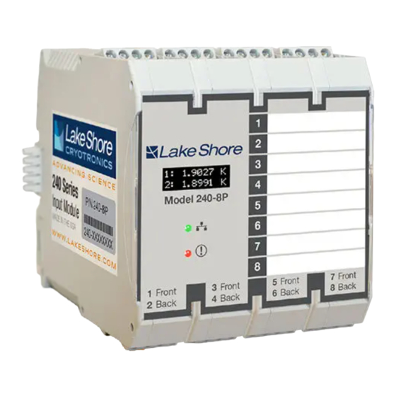
Model 240-8P
sales@lakeshore.com
support@lakeshore.com
www.lakeshore.com
P/N 119-241
Fax: (614) 891-1392
Telephone: (614) 891-2243
8 November 2023
|
www.lakeshore.com
Advertisement

Related Manuals for Lakeshore 240 Series

Summary of Contents for Lakeshore 240 Series
- Page 1 User’s Manual 240 Series Cryogenic Sensor Input Module Model 240-2P Model 240-8P Lake Shore Cryotronics, Inc. sales@lakeshore.com 575 McCorkle Blvd. support@lakeshore.com Fax: (614) 891-1392 Westerville, Ohio 43082-8888 USA www.lakeshore.com Telephone: (614) 891-2243 Methods and apparatus disclosed and described herein have been developed solely on company funds of Lake Shore Cryotronics, Inc.
- Page 2 Product (such as probe tips and cables, probe holders, sample tails, rods and holders, ceramic putty for mounting samples, Hall sample cards, Hall sample enclosures, etc.); or, (d) non-Lake Shore branded Products that are inte- grated with the Product. 240 Series Input Module...
- Page 3 COMPLIANCE AND CERTIFICATIONS by this product or its failure to work, or any other incidental or conse- See https://www.lakeshore.com/compliance/. quential damages. Use of our product implies that you understand the Lake Shore license agreement and statement of limited warranty.
- Page 4 240 Series Input Module...
-
Page 5: Table Of Contents
2.5.5 System Non-Linearity ............13 www.lakeshore.com... - Page 6 4.3.5 Readings Pane and 240 Series Front Display....... . .
- Page 7 7.8.5 Restocking Fee ..............53 www.lakeshore.com...
- Page 8 240 Series Input Module...
-
Page 9: Chapter 1: Introduction
Lake Shore provides a utility called MeasureLINK , which makes loading tempera- ture curves into the 240 Series input module a very simple process. The program con- Utility figures the module and copies curves from formatted files into the 240 Series input module. -
Page 10: Sensor Selection
T > 2 K & B " 10 T Rox™ RX-202 0.3 K to 40 K Non-HT version maximum temperature: 325 K Low temperature specified with self-heating error: " 5 mK TABLE 1-1 Sensor temperature range 240 Series Input Module... -
Page 11: Specifications
1.3 Specifications Full specifications are provided on our website. Please see the Technical Specifica- tions page at: https://www.lakeshore.com/240/. Feature Description Operating temperature 15 °C to 35 °C at rated accuracy; -20 °C to 50 °C at reduced accuracy Storage temperature -40 °C to 85 °C... -
Page 12: Safety Summary And Symbols
Lake Shore Cryotronics, Inc. assumes no liability for cus- tomer failure to comply with these requirements. The 240 Series input module protects the operator and surrounding area from elec- tric shock or burn, mechanical hazards, excessive temperature, and spread of fire from the instrument. - Page 13 Three-phase alternating current (power line) yellow; symbol and outline: black Earth (ground) terminal CAUTION or WARNING: See instrument documentation; background color: yellow; Protective conductor terminal symbol and outline: black Frame or chassis terminal On (supply) Off (supply) FIGURE 1-2 Safety symbols www.lakeshore.com...
- Page 14 CHAPTER 1: Introduction 240 Series Input Module...
-
Page 15: General
240 Series input module are not suitable to read some sensors over their entire temperature range. Lake Shore sells calibrated sensors that operate down to 20 mK, but the 240 Series input module is limited to above 1 K in its standard configu- ration. -
Page 16: Environmental Conditions
A sensor package generally determines its size, thermal and electrical contact to the outside, and sometimes lim- its temperature range. When choosing a sensor, consider the mounting surface and how leads will be thermally anchored. 240 Series Input Module... -
Page 17: Sensor Calibrations
A calibrated sensor is required when a sensor does not follow a standard curve and you wish to display in temperature. Otherwise the 240 Series input module will operate in sensor units like ohms or volts. The 240 Series input module may not work over the full temperature range of some sensors. -
Page 18: Sensor Installation
Good gasket materials are soft, thin, and have good thermal conductivity. They must also withstand the environ- mental extremes. Indium foil and cryogenic grease are good examples. 240 Series Input Module... -
Page 19: Contact Pressure
Thermal anchor (bobbin) Cryogenic wire (small diameter, large AWG) Sensor Second stage and Heater sample holder (wiring not shown for clarity) Drawing not to scale Optical window (if required) FIGURE 2-1 Typical sensor installation in a mechanical refrigerator www.lakeshore.com... -
Page 20: Lead Soldering
(or one cannot be easily made), one alternative is to wrap several layers of super-insulation (aluminized mylar) loosely between the vacuum shroud and load. This reduces radiation transfer to the sample space. 240 Series Input Module... -
Page 21: Consideration For Good Control
Carefully monitor temperature sensitivity. Sensitivity not only affects control stabil- ity, but it also contributes to the overall control system gain. The large changes in sen- sitivity that make some sensors so useful may make it necessary to retune the control loop more often. www.lakeshore.com... - Page 22 CHAPTER 2: Cooling System Design and Temperature Control 240 Series Input Module...
-
Page 23: General
Check off each item on the packing list as it is unpacked. Instruments themselves may be shipped as several parts. The items included with the 240 Series input module are listed below. Contact Lake Shore immediately if there is a shortage of parts or accessories. Lake Shore is not responsi- ble for any missing items if they have not been notified within 60 days of shipment. -
Page 24: Physical Installation
CHAPTER 3: Installation 3.3 Physical The 240 Series input module has been specifically designed to mount on a DIN rail. To minimize shock hazard, the instrument is equipped with a grounded connection to Installation the DIN rail. Mount the input module vertically, and connect the DIN rail to an electri- cal ground. -
Page 25: Backplane
Up to 20 modules can be chained together to share power. Use caution when chaining together RS-485 com- munication connectors; the maximum amount of connectors for RS-485 communi- cation depends on your configuration. FIGURE 3-3 Backplane connectors www.lakeshore.com... -
Page 26: Power And Rs-485 Connections
A– A– FIGURE 3-5 Backplane power connection Certified PROFIBUS connections require 1 meter of cable between each slave module, because of potential conflicts due to reflections. Using the backplane is not recom- mended for PROFIBUS connections. 240 Series Input Module... -
Page 27: Rs-485 Grounding And Shielding
Phoenix’s PSI-Terminator-PB-TBUS may be a convenient way to connect the power and PROFIBUS cabling to meet the applicable PROFIBUS requirements, especially when the modules are first or last on the PROFIBUS segment. www.lakeshore.com... -
Page 28: Diode/Resistor Sensor Inputs
The suggested wire size is between 16 AWG and 28 AWG. The conductor cross section for solid wire, stranded wire, or ferrules is mini- mum of 0.14 mm and a maximum of 1.5 mm If two conductors are inserted, the wire sizes should be equivalent, 240 Series Input Module... -
Page 29: Input Configuration
3.5.2 Input The diagram below illustrates the features of the 240 Series input modules. The loca- tion of each input is listed on the front of the module. Configuration Power and communication connector (4-pin connector) USB port Integrated rear DIN rail... -
Page 30: Sensor Polarity
A shield is most effective when it is near the measurement potential so the 240 Series input module offers a shield at measurement common. The shield of the sensor cable should be connected to the shield pin of the input connector. The shields should not be connected to earth ground near the module. -
Page 31: Two-Lead Sensor Measurement
Do not attach more than one cable shield at the other end of the cable Run different inputs and outputs in their own shielded cable Use twisted wire inside the cooling system Consider ground strapping the instrument chassis (DIN rail) to other instruments or computers www.lakeshore.com... - Page 32 CHAPTER 3: Installation 240 Series Input Module...
-
Page 33: Chapter 4: Configuration
FIGURE 4-1 Model 240-2P and Model 240-8P front panels 4.2 Configuration 4.2.1 Physical The 240 Series input module must be configured via a USB to PC connection. If you do not have one already, a micro-USB cable is included in the optional 240 Series acces- Connection sory kit (240-ACC-KIT), which must be purchased separately. -
Page 34: Programming Using Measurelink
PC once the module is disconnected. In most cases, commands and configura- MeasureLINK™ tions are applied to the Model 240 instantly, and settings are saved to the 240 Series input module’s internal memory. Once configuration is complete, it is safe to discon- nect the 240 Series input module. -
Page 35: Measurelink™ Interface Overview
3. The readings pane is located on the right of the screen. This area provides real- time readings for all inputs in the module. FIGURE 4-3 The MeasureLINK™ interface 4.3.3 Module Settings System-level settings for the 240 Series input module are set on the Module Settings screen. 4.3.3.1 Module Settings Setting... -
Page 36: Input Settings
4.3.4 Input Settings Configuration options available for each input are listed below. When configuring the 240 Series input module in MeasureLINK™, it is best to start at the top of the screen to configure settings. FIGURE 4-4 The Input settings screen... - Page 37 Sensor Excitation without deleting the curve that is stored for provided to the sensor that input. TABLE 4-3 Input settings 4.3.4.2 Sensor Setup The 240 Series input module supports the following sensors: Sensor type Input range Excitation Curve format Example sensors Resistive—Negative...
- Page 38 PLC’s capabilities, thus maximiz- ing the performance of the module. High speed mode is not available on the 8-input version of the 240 Series input module. 4.3.4.4 Display Units The 240 Series input module has an integrated front screen that displays two input readings.
-
Page 39: Readings Pane And 240 Series Front Display
The current status of the measurement inputs can be seen in two different locations: and 240 Series Front 240 Series input module front OLED display: shows two readings based on the display units. Whether these readings are dedicated or cycling depends on the Display number of inputs in the module. -
Page 40: Evaluation Kit (Optional)
Cernox temperature range, to be used as a rough approximation of these sensors. This product can be useful if you’d like to see how the 240 Series input module handles communicating and displaying a particular temperature range, or if you’d like to see how the 240 Series input module autoranges. -
Page 41: Chapter 5: Operation
The slave device then responds with any input readings that it has. Not all devices have both outputs and inputs, so for an instrument like the 240 Series input module that only has inputs, the master will send a communication telegram that just requests readings. -
Page 42: Establishing Communication
If not using all eight slots, leave the unused slots empty. FIGURE 5-1 is an example (using the Siemens TIA Portal® PLC software) showing a 240 Series input module con- figured to send two readings back. - Page 43 If the master does not communicate with the module before the watchdog timer expires, the module goes back into the parameterization state and waits to be reconfigured. The communication LED on the front panel of the module is solid green when it is in the data exchange state. www.lakeshore.com...
-
Page 44: Usb Interface
A special ASCII character, line feed (LF 0AH), is used to indicate the end of a mes- sage string. This is called the message terminator. The 240 Series input module will accept either the line feed character alone, or a carriage return (CR 0DH) followed by a line feed as the message terminator. -
Page 45: Message Flow Control
5.3.4 Message Flow It is important to remember that the user program is in charge of the USB communi- cation at all times. The 240 Series input module cannot initiate communication, Control determine which device should be transmitting at a given time, or guarantee timing between messages. -
Page 46: Command Summary
Factory Defaults Cmd PROFISTAT? PROFIBUS Connection Status Query FILTER Input Filter Parameter Cmd RDGST? Input Reading Status Query FILTER? Input Filter Parameter Query SRDG? Sensor Units Input Reading Query FRDG? Fahrenheit Reading Query TABLE 5-3 Command summary 240 Series Input Module... -
Page 47: Interface Commands
TABLE 5-4 Interface commands key IDN? Identification Query IDN? [term] Input Returned <manufacturer>,<model>,<instrument serial>, <firmware version>[term] Format s[4],s[11],s[7],n.n <manufacturer> Manufacturer ID <model> Instrument model number <instrument serial> Instrument serial number <firmware version> Instrument firmware version Example LSCI,MODEL240-2P,1234567,1.0 www.lakeshore.com... - Page 48 Accepting ‘0’ for the input number is only available on firmware version 2.3 or later. CRVDEL Curve Delete Command CRVDEL <input>[term] Input Format <input> Specifies a user curve to delete. Valid entries: 1-8. Example CRVDEL 1[term] deletes User Curve for input 1. 240 Series Input Module...
- Page 49 Returns a standard or user curve data point. DFLT Factory Defaults Command DFLT 99 [term] Input Remarks Sets all configuration values to factory defaults and resets the instrument. The “99” is included to prevent accidentally setting the unit to defaults. www.lakeshore.com...
- Page 50 INNAME? Sensor Input Name Query INNAME? <input>[term] Input Format <input> Specifies which input to query: 1-8. Returned <name>[term] Format s[15] (refer to command for description) 240 Series Input Module...
- Page 51 Input Type Parameter Query INTYPE? <input>[term] Input Format <input> Specifies which input to query: 1-8. Returned <sensor type>,<autorange>,<range>,<current reversal>,<units>, <disabled/enabled>[term] Format n,n,n,n,n,n (refer to command for description) Remarks If autorange is on, the returned range parameter is the currently auto-selected range. www.lakeshore.com...
- Page 52 Configures the number of PROFIBUS slots for the instrument to present to the bus as a modular station. The lowest <count> slot numbers are used. PROFINUM? PROFIBUS Slot Count Query PROFINUM? [term] Input Returned <count>[term] Format n (refer to command for description) 240 Series Input Module...
- Page 53 The integer returned represents the sum of the bit weighting of the input status flag bits. A “000” response indicates a valid reading is present. Bit weighting Status indicator invalid reading temp underrange temp overrange sensor units under range sensor units overrange www.lakeshore.com...
- Page 54 ±nnnnnn Or if all inputs are queried: ±nnnnnn, ±nnnnnn, ±nnnnnn, ±nnnnnn, ±nnnnnn, ±nnnnnn, ±nnnnnn, ±nnnnnn[term] Remarks Also see the RDGST? command. Accepting ‘0’ for the input number is only available on firmware version 2.3 or later. 240 Series Input Module...
-
Page 55: Chapter 6: Options And Accessories
Accessories are devices that perform a secondary duty as an aid or refinement to the primary unit. Refer to the Lake Shore Temperature Measurement and Control Catalog for details. A list of accessories available for the 240 Series input module is as follows: Model... - Page 56 CHAPTER 6: Options and Accessories 240 Series Input Module...
-
Page 57: Chapter 7: Service
5. Check that the USB driver is installed properly and that the device is functioning. In Microsoft Windows®, the device status can be checked using Device Manager by right-clicking Lake Shore Temperature Module under Ports (COM & LPT) or Other Devices and then clicking Properties. www.lakeshore.com... -
Page 58: Factory Reset
It is sometimes necessary to reset instrument parameter values or to clear the con- tents of curve memory. Both are stored in nonvolatile memory. Instrument calibra- tion is not affected. 7.4 Error The following are error messages that may be displayed by the 240 Series input mod- ule during operation: Messages Message... -
Page 59: Firmware Updates
Firmware updated firmware into the instrument. See section 4.3.3. 7.8 Summary of This section outlines the internal memory devices used inside the 240 Series input module, and provides an explanation of the types of data they contain. Internal Memory Devices... -
Page 60: Technical Inquiries
Instrument Service TABLE 7-3 Contact information 7.9.2 Return of The 240 Series input module is packaged to protect it during shipment. Equipment The user should retain any shipping carton(s) in which equipment is originally received, in the event that any equipment needs to be returned. -
Page 61: Rma Valid Period
Lake Shore. Equipment serviced out-of-warranty will be returned FOB Lake Shore. 7.9.5 Restocking Fee Lake Shore reserves the right to charge a restocking fee for items returned for exchange or reimbursement. www.lakeshore.com... - Page 62 CHAPTER 7: Service 240 Series Input Module...
Need help?
Do you have a question about the 240 Series and is the answer not in the manual?
Questions and answers