
Related Manuals for Lakeshore 240 Series

Summary of Contents for Lakeshore 240 Series
- Page 1 Quick Start Guide 240 Series Cryogenic Sensor Input Module Model 240 Quick Start Guide...
-
Page 2: Safety Precautions
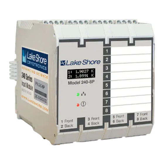
Operation of any electrical instrument in such an environment The 240 Series input module protects the operator and constitutes a definite safety hazard. surrounding area from electric shock or burn, mechanical... - Page 3 Introduction Power and communication connector (4-pin connector) This guide provides basic USB port information for getting started with your input modules. For Integrated further information, please see rear DIN rail connections the Model 240 user’s manual. USB port Cryogenic temperature Front-mounted sensor inputs OLED screen...
- Page 4 Unpacking Packing list Items included with Model 240 input module: Inspect shipping containers for external damage before opening them. 240 Series input module „ Photograph any container that has significant 2 or 8 sensor input connectors, 5-pin terminal plug „...
-
Page 5: Sensor Input Connection
Power and Communication Sensor Input Connection Connection For best results, voltage leads (V+ and V-) and current leads (I+ and I-) should be twisted together. The twisted To minimize shock hazard, the instrument is equipped pairs of voltage and current leads should then be with a grounded connection to the DIN rail. -
Page 6: Usb Connection
NOTE: Make sure to properly seat connectors. Physical Installation When removing a sensor, use a screwdriver to gently The 240 Series input module has been specifically remove the connector. designed to mount on a DIN rail. To minimize shock hazard, the instrument is equipped with a grounded USB Connection connection to the DIN rail. - Page 7 Startup Once you have placed the Model 240 in its intended location, you can begin setting up the instrument. The steps that follow will take you through to displaying measurements. This is just the beginning of what is possible with the Model 240. For additional features, please see the Model 240 user’s manual.
- Page 8 Model 240 Quick Start Guide Select the input module from the drop down menu and click Connect. Click the Input at the left of the screen to configure the sensor settings.
- Page 9 Load the sensor calibration file (under Sensor setup) that matches the sensor by navigating to the appropriate file. Model 240 Quick Start Guide...
- Page 10 10. Under Reporting units, select either Sensor units or a temperature unit. 11. Live readings from your connected sensors should now be displayed at the right of the screen, as well as on the front OLED display of the 240 Series input module.
-
Page 11: Evaluation Kit
NOTE: The accuracy rating of the trimpot is 10%, so the measured resistance and temperature value may not align exactly with the markings on the dial. Please do not use the sensor simulator as a method for verifying accuracy of the 240 Series input module. - Page 12 NOTE: The fingers can be fragile. Please handle the assembled set by the terminal connector when connecting and disconnecting to the 240 Series input module. Plug the terminal connector into the desired input of the 240 Series input module. The switch should face toward the front of the module.
- Page 13 Analog input Measurement performance: Cernox Platinum Diodes Measurement Electronic resolution accuracy Sensor units Ohms (Ω) Volts (V) 2 K (with CX-1050) 0.06 mK ±0.57 mK 4.5 K (with CX-1050) 0.2 mK ±2.1 mK Cernox Platinum Diodes 4.2 K (with DT-670) 0.6 mK ±15 mK Measurement...
-
Page 14: Contacting Lake Shore
5:00 p.m. EST, excluding holidays and company shut down days. Contact Lake Shore Service through any of the means listed below. However, the most direct and efficient way is to complete the online service request form at http://www.lakeshore.com/Service/. Lake Shore Service Lake Shore Cryotronics Instrument Service Department 575 McCorkle Blvd.
Need help?
Do you have a question about the 240 Series and is the answer not in the manual?
Questions and answers