
Related Manuals for RDZ PDC-GTM-RES


Summary of Contents for RDZ PDC-GTM-RES
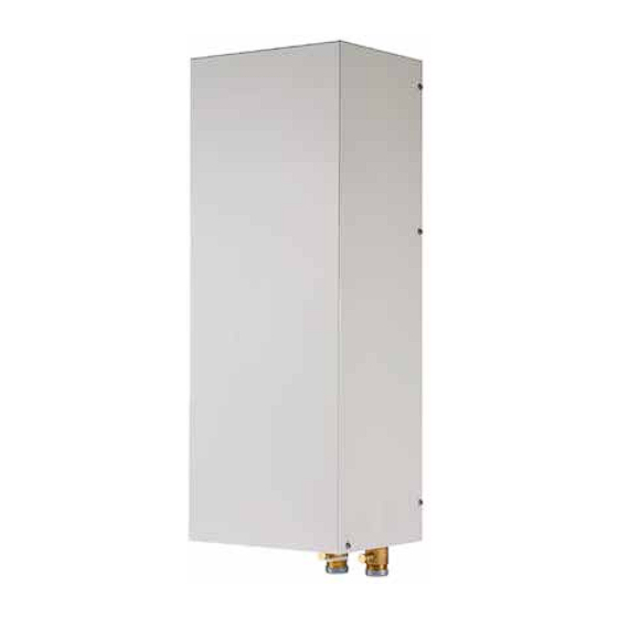
- Page 1 Chiller & Heat Pumps PDC-GTM-RES Supplementary Electric Heater for Monoblock Heat Pump Green Tech series - R32 5-9 kW INSTALLATION AND OWNER’S MANUAL...
-
Page 3: Installation
PDC-GTM-RES INSTALLATION AND OWNER’S MANUAL INSTALLATION Thank you very much for purchasing our product. Before using the unit, please read this manual carefully and keep it for future reference. -
Page 4: About The Documentation
INSTALLATION & OWNER’S MANUAL - MONOBLOC BACKUP HEATER 1.0 ABOUT THE DOCUMENTATION This document is prepared for authorised installers, read this document carefully before installation. keep this manual in a handy place for future reference. Improper installation or attachment of equipment or accessories could result in electrical shock, short circuit, leaks, fire or other damage to the equipment. -
Page 5: Preparing Water Piping
INSTALLATION & OWNER’S MANUAL - MONOBLOC BACKUP HEATER • Mind the following spacing installation guidelines: 3.3 Preparing electrical wiring Unit mm 3.3.1 Overview of electrical connections for external and internal actuators Maximum Item Description Wires running >500 current Interconnection cable Interconnection cable between backup heater 0.2A... - Page 6 4 INSTALLATION 4.1 Opening the units 4.1.1 To open the backup heater 4.2 Mounting the backup heater 4.2.1 To install the backup heater 2) Fix the wall bracket to the backup heater with M4 1) Fix the wall bracket to the wall with M8 screws. screws.
-
Page 7: Connecting The Electrical Wiring
3) Hang the backup heater onto the wall bracket. Make INFORMATION sure it is fixed properly. Inside the backup heater, an automatic air purge valve 4) Fix the bottom of the backup heater to the wall with isinstalled. During operation make sure the automatic an M8 expansion screws. -
Page 8: To Connect The Backup Heater Power Supply
1) Insert the wiring from the bottom of the backup WARNING heater. 2) Inside the backup heater, route the wiring as follows: If a tank with a builtin electrical booster heater is part of the system, use a dedicated power circuit for the backup heater and booster heater. -
Page 9: Starting Up The System
4.4.3 To connect the backup heater kit to the outdoor unit For the sensor, connect 2 wires between backup heater terminals XT20M/5+6 and control box connector T1. For the connection with the control box, connect 3 wires between backup heater terminals XT20/1+2 and control box terminals XT9/31+39. - Page 11 16110600000085 V3.0...
- Page 12 CLICK | SCAN qr.rdz.it/?qr=P642 FAG0FC002BZ.00 03/2023...
Need help?
Do you have a question about the PDC-GTM-RES and is the answer not in the manual?
Questions and answers