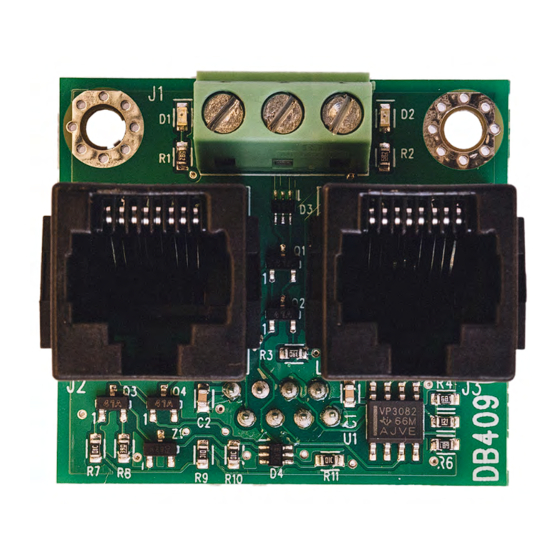
Summary of Contents for DAAB DB409
- Page 1 INSTRUCTION MANUAL DAAB INTERFACE CARD DB409 FOR FREQUENCY CONVERTER VFD-EL For DAAB Automatic control unit EP104 version 4.08 EP105 FAAC Nordic AB BOX 125, SE-284 22 PERSTORP SWEDEN, +46 435 77 95 00, support@faac.se www.faac.se...
-
Page 2: Preparations Before Connection
The cable in X12 is removed Connection The frequency converter being connected to the DB409 must be a DELTA VFD-EL. This frequency converter is based on negative logic. Refer to the following pages for full details regarding signals and connecting electric motors. - Page 3 The cable in X12 is removed Connection The frequency converter being connected to the DB409 must be a DELTA VFD-EL. This frequency converter is based on negative logic. Refer to the following pages for full details regarding signals and connecting electric motors.
- Page 4 DAAB INTERFACE CARD DB409 INSTRUCTION MANUAL • Wiring diagram for one motor A Mains connection B Control panel C NPN/PNP D AVI/ACI E Terminal block F RS485 (RJ-45) G Motor connection Important: Power BEFORE connection takes place the Must not be used!
- Page 5 DAAB INTERFACE CARD DB409 INSTRUCTION MANUAL • Circuit diagram for two motors A Mains connection B Control panel C NPN/PNP D AVI/ACI E Terminal block F RS485 (RJ-45) G Motor connection Important: BEFORE connection takes place, the following cables must be...
- Page 6 • Modification of the motor winder The following criteria must be met in order to use the DAAB motor winder with the frequency converter: • If mechanical limit switches are used, the limit switch cams must be wider than normal.
- Page 7 DAAB INTERFACE CARD DB409 INSTRUCTION MANUAL • Setting of frequency converter Note that the switches above the terminal block must be in the upward position! (NPN/AVI) Revision 7...
- Page 8 DAAB INTERFACE CARD DB409 INSTRUCTION MANUAL Channel setting with encoder, DB405 For the automatic control unit to measure current and output correctly, C202 must be set to 4, frequency converter. When a frequency converter is used with the automatic control unit, EP104 or E105, a load guard with personal protection cannot be used.
- Page 9 DAAB INTERFACE CARD DB409 INSTRUCTION MANUAL Channel settings with mechanical limit switches. In the case of mechanical limit switches, no ramp-down angles are calculated and suitable run-on times must instead be tested in commissioning. Channels for setting of run-on time.
- Page 10 DAAB INTERFACE CARD DB409 INSTRUCTION MANUAL Channel list, Frequency converter, F-channels Name Range Factory Setting F001 Communication with frequency converter 0 - 1 Communication disabled Communication activated F002 Acceleration time from closed position 0.5-9.9 seconds motor 1 and 2 (from 0-100Hz)
- Page 11 DAAB INTERFACE CARD DB409 INSTRUCTION MANUAL Name Range Factory Setting F030 * Choice of ratio for motor 1 0 - 9 Not selected, in this position the motor only rotates at 25Hz MK with pulleys 40/71 (ratio 1318:1) MK with pulleys 50/71 (ratio 1098:1)


Need help?
Do you have a question about the DB409 and is the answer not in the manual?
Questions and answers