
Related Manuals for Vivo STAND-RACE1B

Summary of Contents for Vivo STAND-RACE1B
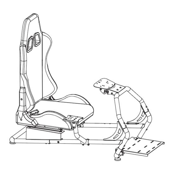
- Page 1 Racing Simulator Cockpit SKU: STAND-RACE1B/BL Instruction Manual Assembly Video & Product Info www.vivo-us.com/products/stand-race1b...
- Page 2 If you do not understand these directions, or if you have any doubts about the safety of the installation, please contact our product support team at 309-278-5303 or help@vivo-us.com for further assistance. Check carefully to make sure there are no missing or defective parts. Improper installation may cause damage or serious injury. Do not use this product for any purpose that is not explicitly specified in this manual.
-
Page 3: Package Contents
Package Contents A (x1) D (x2) B (x2) C (x1) Support Bar Front Support Side Support Bar Rear Support Bar Frame Spacer E(x1) F (x1) G (x1) H (x1) Right Brace Left Brace Footrest Wheel Mount I (x1) J (x1) K (x1) Right Chair Left Chair... -
Page 4: Included Hardware & Tools
Included Hardware & Tools S-A (x4) S-B (x4) S-C (x4) S-D (x22) S-E (x4) Spacer M8x30mm Hex M5x8mm M8x16mm M8x30mm Head Screw with Screw Screws Screws Washers S-F (x2) S-G (x2) S-H (x2) S-I (x2) T-A (x1) M8x60mm M6x15mm M8x50mm M8 Nut 5mm Allen Screws... -
Page 5: Assembly Steps
ASSEMBLY STEPS STEP 1 Screw two Foot Pads (O) into the underside of Front Support Frame (A). Place one Support Bar Spacer (D) onto the front, angled end of each Side Support Bar (B), then connect to the Front Support Frame (A) using M8x60mm Screws (S-F). Tighten using 5mm Allen Wrench (T-A). - Page 6 STEP 2 Screw remaining Foot Pads (O) into Rear Support Bar. Then insert the Side Support Bars (B) into the Rear Support Bar (C), and secure using M8x16mm Screws (S-D) and 5mm Allen Wrench (T-A). S-D (x8) STEP 3 Remove pre-installed Screws (A-1) from Front Support Frame (A). Assemble Right and Left Braces (E, F) to the frame using previously removed Screws (A-1), M8x16mm Screws (S-D) and 5mm Allen Wrench (T-A).
- Page 7 STEP 4 Install the Footrest (G) to the Front Support Frame (A) using M8x16mm Screws (S-D) and 5mm Allen Wrench (T-A). Ensure Screws go into the rear mounting holes on Footrest. Insert Screws into the rear mounting holes on Footrest S-D (x2) Insert M8x16mm Screws (S-D) into the front holes of Footrest (G) and Front Support Frame (A) to hold Footrest at one of three heights, as shown below.
- Page 8 STEP 5 Attach Wheel Mount (H) to Front Support Frame (A) using M8x16mm Screws (S-D) and 5mm Allen Wrench (T-A). S-D (x2) Adjust the wheel mount height and angle by removing the pre-installed bolts with washers from the sides, then reinstall while holding the mount at the desired height and angle.
- Page 9 STEP 6 Extend the Slider (I-1) on Right Chair Support with Lock (I) by lifting on the Lever (I-2) and pulling forward. Pull and extend Slider (J-1) forward on Left Chair Support (J).
- Page 10 STEP 7 Connect Right and Left Chair Supports (I, J) to the Chair Seat (K) using Spacers (S-A) and M8x30mm Screws (S-E) into to front holes on Sliders (I-1, J-1) with 5mm Allen Wrench (T-A). S-A (x2) S-E (x2) Slide Supports (I, J) forward to reveal rear mounting hole. Secure using Spacers (S-A), M8x30mm Screws (S-E), and 5mm Allen Wrench.
- Page 11 STEP 8 Mount Chair Seat (K) with Supports to assemble frame using M8x16mm Screws (S-D) with 5mm Allen Wrench (T-A). S-D (x4) STEP 9 Assemble Chair Back (L) to Side Brackets (K-1) on Chair Seat (K) using M8x30mm Hex Head Screw with Washers (S-B) and a Phillips screwdriver.
- Page 12 STEP 10.1 The Shifter Mount can be installed on either the right or left side, based on your preferences. Follow the steps outlined below and on the next page to assembly to your desired side. OPTION A: Right Side Shift Lever Attach Shifter Mount (Q) to the top of Shifter Support Bar (P) using M6x15mm Screws (S-G), making sure the long end of Mount is in the back, and tighten with a Phillips screwdriver.
- Page 13 STEP 10.2 OPTION B: Left Side Shift Lever Attach Shifter Mount (Q) to the top of Shifter Support Bar (P) using M6x15mm Screws (S-G), making sure the long end of Mount is in the back, and tighten with a Phillips screwdriver. S-G (x2) Connect the Shifter Support Bar (P) to the left side of the frame using M8x50mm Screws (S-H) and M8 Nuts (S-I).
-
Page 14: Cable Management
STEP 11 Adjust the mount angle by removing the pre-installed bolts from the sides using 5mm Allen Wrench (T-A). Reinstall while holding the mount at the desired angle. RIGHT SIDE ASSEMBLY Default Position Tilted LEFT SIDE ASSEMBLY Default Position Tilted CABLE MANAGEMENT Use Cable Clips (R) and Zip Ties (S) to organize and secure cables. -
Page 15: Seat Adjustment
SEAT ADJUSTMENT Use the levers on the right side of the assembled cahir to adjust the seat angle and position. OTHER ADJUSTMENTS... - Page 16 LAST UPDATED: 10/31/2023 REV4 Need Help? Get In Touch Monday-Friday from 7:00am-7:00pm CST help@vivo-us.com www.vivo-us.com 309-278-5303 Chat live with an agent! FOR MORE GREAT VIVO PRODUCTS, CHECK OUT OUR WEBSITE AT: WWW.VIVO-US.COM VIVO-us @vivo_us...
Need help?
Do you have a question about the STAND-RACE1B and is the answer not in the manual?
Questions and answers