Table of Contents
Advertisement
Advertisement
Table of Contents

Related Manuals for ersa IR 650 A

Summary of Contents for ersa IR 650 A
- Page 1 Operating Instructions ERSA IR 650 A and PL 650 A Semi-Automatic SMD/BGA Rework System ERSA GmbH Leonhard-Karl-Str. 24 97877 Wertheim / Germany Service Phone +49 9342/800-147 +49 9342/800-256 Email service.tools@ersa.de Internet www.ersa.com Document 3BA00143 Rev.2...
-
Page 2: Table Of Contents
8. Maintenance 8.1 Cleaning 8.1.1 IR 650 A 8.1.2 PL 650 A 8.2 Replacing a silicon suction cup on the IR 650 A 9. Spare parts and wearing parts 9.1 ERSA IR 650 A 9.2 ERSA PL 650 A ERSA IR / PL 650 A / Page 2... - Page 3 Neither the complete documentation nor parts of it may be reproduced or used for competitive purposes without prior permission of ERSA GmbH. Actions to the contrary constitute an obligation for compensation of damages. Document 3BA00143 Rev.2 ERSA IR / PL 650 A / Page 3...
-
Page 4: Introduction
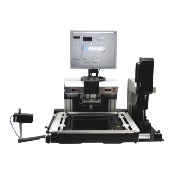
The integrated reflow process camera rounds out the process reliability aspects of the IR 650 A. The IR 650 A is ideally supplemented with the PL 650 A placement system. With the PL 650 A secure placement of even the smallest, multi-position components succeeds in no time. -
Page 5: Proper Use
1.3 Proper use The ERSA IR / PL 650 A rework system has been built in accordance with the state of the art and stan- dard health and safety regulations. Residual hazards can exist with the system, particularly if it is oper- ated improperly by untrained personnel, or if it is used for purposes for which it is not intended (proper use). -
Page 6: Technical Data
Maximum heating element surface 350 x 470 mm Vacuum nozzle switching point IR heating element wavelength 2 - 5 µm Up to 15 mm above the upper edge of the PCB. ERSA IR / PL 650 A / Page 6 Document 3BA00143 Rev.2... -
Page 7: Ersa Pl 650 A
Component placement force app. 2 N for Auto Pick&Place, or position controlled. Illumination LED row light (each side separately adjustable for component and PCB) LED ring light for RPC camera (adjustable) Document 3BA00143 Rev.2 ERSA IR / PL 650 A / Page 7... -
Page 8: Safety Instructions
Operating Instructions ERSA IR / PL 650 A 3. Safety instructions 3.1 Aggregates and interfaces The interfaces and aggregates of the IR 650 A = PL 650 A are shown in the following photo. Video output USB interface DIGITAL 2000 A... - Page 9 Switch for illumination The switch activates or deactivates the system illumination. IR 650 A display The display shows the current actual temperature of the selected temperature sensor. Document 3BA00143 Rev.2 ERSA IR / PL 650 A / Page 9...
- Page 10 ERSA IR / PL 650 A Video output: Two cinch sockets are located on the rear of the IR 650 A. The video signal from the RPC camera and the PL camera are available on these sockets. This signal is transmitted to the video inputs of the FALCON Frame Grabber card in the PC via two video cables.
-
Page 11: Safety Instructions For Handling The System
The device contains voltage-conducting parts. There is a risk of fatal injury if inexpe- rienced personnel work on the unit. Only experienced and qualified electricians may perform repair work. Document 3BA00143 Rev.2 ERSA IR / PL 650 A / Page 11... -
Page 12: Transport, Storage, Assembly, And Disposal
Please contact your supplier if the listed components are damaged or incomplete. 4.2 Transport and storage IR 650 A and PL 650 A are each delivered on a pallet in a stable box enclosure. Only use the original packaging for transport and interim storage of the systems. -
Page 13: Assembly
Remove the IR 650 A from the packaging. Remove the topside of the enclosure, have two people lift the device under the base plate. Place the IR 650 A on the work platform. 200 - 300 mm of work platform should remain free in front of the device. -
Page 14: Mechanical Connections
Place the rest stand on the IR 650 A. Take the PL 650 A device out of its packaging: Position the PL 650 A to the right next to the IR 650 A on the work platform. Connect the IR 650 A and the PL 650 A to the base plate using the screws (2x M6) provided. -
Page 15: Electrical Connections
ERSA IR / PL 650 A 4.3.2 Electrical connections Attention: Ensure that the master switch on the IR 650 A is switched off, before connecting the electrical systems! Connect the vacuum feed line of the PL 650 A to the IR 650 A. -
Page 16: Disposal
Operating Instructions ERSA IR / PL 650 A Connect the two video sockets on the rear of the IR 650 A to the FALCON Frame Grabber that you have previously installed in your Connect the USB cable, type A-B to one of your PC‘s USB con- nections. -
Page 17: Commissioning
ERSA IR / PL 650 A 5. Commissioning 5.1 Switching on for the first time Switch on the master switch on the IR 650 A and on the PL 650 A. After a brief self-test the devices are ready for operation. 5.2 IRSoft installation... -
Page 18: Function Description
Soft view. The interface is basically divided into three parts. The Operator controls are on the left side, the profile setting view is on the right side, the parameter windows are below. ERSA IR / PL 650 A / Page 18 Document 3BA00143 Rev.2... -
Page 19: Device Controls
“Head down” key. Pushing the slider triggers the corresponding actuators in the Placer, use the mouse wheel to finely adjust the slider for the input focus. Document 3BA00143 Rev.2 ERSA IR / PL 650 A / Page 19... -
Page 20: Parameter Window
With the IR650A the configuration of the upper and lower heating elements is displayed, with the IR550A, the setting of the apertures is displayed. ERSA IR / PL 650 A / Page 20 Document 3BA00143 Rev.2... -
Page 21: Measured Value And Threshold Value Sensors
In the “System settings” window, all functions are listed with which the behavior of the system can be specifically changed. Note: All options are immediately active and do not need any special transmission or activation in the device. Document 3BA00143 Rev.2 ERSA IR / PL 650 A / Page 21... -
Page 22: The Status Display
The number of individual status displays is different for IR550A and IR650A. The status messages should be self-explanatory. 6.3.6 The information window System information of the connected IR device is displayed to the user. - Serial number - Firmware version ERSA IR / PL 650 A / Page 22 Document 3BA00143 Rev.2... -
Page 23: Profile Settings
In the Board and Component entry fields the user can activate the appropriate entries. These are then transferred accordingly into the sensors table when activating the profile. Document 3BA00143 Rev.2 ERSA IR / PL 650 A / Page 23... -
Page 24: Setting The Heating Element Configuration
If no search term has been entered, then all available profiles are displayed. The search results can be sorted by double clicking on the header of the desired column. ERSA IR / PL 650 A / Page 24 Document 3BA00143 Rev.2... - Page 25 These provide the user with the possibilities of deleting the profile, or changing the profile and overwrit- ing the profile. The profile can now be transferred into the connected IR device at anytime via the “Activate” button. Document 3BA00143 Rev.2 ERSA IR / PL 650 A / Page 25...
-
Page 26: Desoldering A Component
ERSA IR / PL 650 A 6.5 Desoldering a component Place the PCB in the frame of the IR 650 A and fix it in place. In many cases it is necessary to use the PCB support , to prevent bending the PCB. - Page 27 Then push the start button in the operating controls for the IR 650 A. The IR 650 A now begins to work through the soldering profile. A short time before reaching the melting point the vacuum pump in the IR 650 A starts automatically.
-
Page 28: Placing The Component And Soldering
The placement head picks up the component automatically and moves up. * The photo shows the optional centering station of the PL 650 A ERSA IR / PL 650 A / Page 28 Document 3BA00143 Rev.2... - Page 29 Rotates the placement head around its own axis Changes the amount of light on component and Changes zoom and focus on the placement camera Document 3BA00143 Rev.2 ERSA IR / PL 650 A / Page 29...
- Page 30 PCB, press the Place button The component will then be placed automatically on the PCB. Unlock the placement table. Activate the laser on the IR 650 A. Position the PCB so that the laser points to the middle of the com- ponent.
-
Page 31: The Optimal Profile
Operating Instructions ERSA IR / PL 650 A 6.7 The optimal profile In order to achieve optimal results with the IR 650 A Rework System, the following instructions must be complied with. Solder profile in “Closed Loop Adjustment“ The selected adjustment sensor will generate the selected temperature profile for each assembly, with due consideration of the threshold value sensors. - Page 32 Operating Instructions ERSA IR / PL 650 A ERSA IR / PL 650 A / Page 32 Document 3BA00143 Rev.2...
-
Page 33: Troubleshooting
Operating Instructions ERSA IR / PL 650 A 7. Troubleshooting Document 3BA00143 Rev.2 ERSA IR / PL 650 A / Page 33... -
Page 34: Maintenance
ERSA IR / PL 650 A 8. Maintenance Note: Use only genuine ERSA consumable items and spare parts to maintain reliable function and the warranty. Attention: Device housing parts can still be very hot after the device is switched off. -
Page 35: Spare Parts And Wearing Parts
ERSA IR / PL 650 A 9. Spare parts and wearing parts Although ERSA IR Rework Systems are manufactured with the utmost care, malfunctions or failures of individual components can occur. This list is provided as an aid for quick identification and replacement of defective parts. -
Page 36: Ersa Pl 650 A
Centering station for PL650A 0PL6500-12 Nozzle Ø 0.8 mm 0PL6500-13 Nozzle Ø 1,2 mm 0PL6500-14 Nozzle Ø 3 mm 0PL6500-15 Nozzle Ø 4 mm 0PL6500-16 Nozzle Ø 10 mm 0PL6500-17 ERSA IR / PL 650 A / Page 36 Document 3BA00143 Rev.2...
Need help?
Do you have a question about the IR 650 A and is the answer not in the manual?
Questions and answers