Table of Contents
Advertisement
CARIA SERIES FULL AUTOMATIC PELLET BOILER
CP-12, CP-23, CP-40, CP-60, CP-80, CP-100, CP-150
OPERATION, USE AND MAINTENANCE MANUAL
WITH ADVANCED TOUCH PANEL CONTROLLER
Rev F: August 2020
ARIKAZAN MAK. SAN. TIC. A. S MAK.SAN.TİC.A.Ş
Konya Yolu 29. Km Oğulbey Mah. Kumludere Cad. No:4 06830
GOLBASI/ANKARA
Tel: +90 (312) 615 51 11
Fax: +90 (312) 615 50 56
http://www.arikazan.com
-
info@ARIKAZAN
Advertisement
Table of Contents

Related Manuals for Arikazan CARIA Series


Summary of Contents for Arikazan CARIA Series
- Page 1 CARIA SERIES FULL AUTOMATIC PELLET BOILER CP-12, CP-23, CP-40, CP-60, CP-80, CP-100, CP-150 OPERATION, USE AND MAINTENANCE MANUAL WITH ADVANCED TOUCH PANEL CONTROLLER Rev F: August 2020 ARIKAZAN MAK. SAN. TIC. A. S MAK.SAN.TİC.A.Ş Konya Yolu 29. Km Oğulbey Mah. Kumludere Cad. No:4 06830...
-
Page 2: Table Of Contents
CONTENTS 1. INTRODUCTION ............................2 2. WARNINGS AND CAUTIONS ......................... 3 3. DECLARATION OF CONFORMITY ........................8 4. GUARANTEE AND SERVICE......................... 10 5. GENERAL INFORMATION ..........................13 6. TECHNICAL SPECIFICATION ........................14 6.1 Main Parts ............................14 6.2 Boiler Specifications ..........................16 6.3 Fuel Specification .......................... -
Page 3: Introduction
Dear Customer, Welcome to the Caria Series family which is product of ARIKAZAN MAK. SAN. TIC. A S. Thank you to considerably contribution leaving clean world for the future by choosing environmentally friendly pellet boiler that help to reach the ideal comfort level thanks to its high efficiency and ease of use. -
Page 4: Warnings And Cautions
2. WARNINGS AND CAUTIONS These safety guidelines should be read before operating the system, to avoid incorrect usage that might lead Ø to personal injury or damage to the system. This boiler must be installed in accordance with the local and international rules in force, only in a well Ø... - Page 5 Properties that require a high degree of security for heat supply (the hotel business, process heating, etc.) Ø are to be equipped with dual boiler and/or dual fuel systems. If this requirement is not met, we will deny any claims for consequential damage based on a faulty heating source.
- Page 6 WARNINGS BEFORE MAINTENANCE OR CLEANING PROCESS ELECTRICAL CONNECTION OF BOILER MUST BE CUT OFF. BEFORE CARRYING OUT MAINTENANCE OR CLEANING WAIT AT LEAST 2 HOURS FOR THE BOILER TO COOL DOWN OR UNTIL THE BOILER TEMPERATURE IS BELOW 40⁰C BEFORE OPENING THE CABINET DOOR. THESE COMPONENTS OPERATE AT HIGH TEMPERATURES AND MAY CAUSE PERSONAL INJURY.
- Page 7 Standard operational procedures will apply for restarting under power failure, as where consideration is given for back-up power, this should not only include the boiler but all associated equipment. A backup power supply such as a UPS (battery-based Uninterruptible Power Supply) is required to operate the primary loop pump and dump zone valve if it is of the electrically operated variety.
- Page 8 Recycle the product and the packaging at the end of the operational use period in an appropriate manner. When disposing of the boiler all local waste and disposal directives will apply at the time of action. Do not dispose of the product together with normal waste, Do not burn the product.
-
Page 9: Declaration Of Conformity
3. DECLARATION OF CONFORMITY We hereby make the following declaration under our sole responsibility with regard to the appliance trademark CARIA, models CP12, CP23, CP40, CP60, CP80, CP100, CP150 are in conformity with the requirements of the directives that; · The material used in this appliances have been selected that safety and proper performance of these appliances are ensured and that the materials are resistant to chemical, mechanical and thermal influences to which the appliances will be exposed during their expected service life;... - Page 10 CE Konformitätserklärung CE Declaration of Conformity CE Déclaration de conformité Arikazan Makina Sanayi ve Ticaret A.S. - 06800 Ankara Neus Erkären in alleiniger Verantwortung, dass die Heizkessel-Reihe Declare under our sole responsibility that the boiler series Déclarons sous notre seule responsabilité que le serie des chaudieres...
-
Page 11: Guarantee And Service
Non-compliance will result in voiding of the guarantee. Exclusions Our warranty does not cover every day wear and tear. Additionally, ARIKAZAN MAK. SAN.TIC. A.S. will not accept liability and our warranty will be voided in the event: §... - Page 12 Low quality of the fuel can damage your system and the environment as well. Use only those fuels recommended by ARIKAZAN MAK.SAN. TIC. A.S. and Caria range of boilers are designed to burn fuel to ENplus A1 grade of 6 mm wood pellet.
- Page 13 For all boiler installations, all essential mechanical and electrical safety items must be installed to the heating system in compliance with local regulations and standards. ARIKAZAN MAK.SAN. TIC. A.S. shall not be responsible for any damage, loss and any undesired outcomes of such negligence. In such a case, warranty will be cancelled. The boiler is covered by warranty for a period of 2 (two) years beginning from the date of commissioning;...
-
Page 14: General Information
The burner is equipped by an automatic grate cleaning system. Automatic ash discharge and heat exchanger cleaning systems are all included to the Caria series pellet boiler The nameplate is positioned on the rear panel of the casing of the boiler and shows the technical information and... -
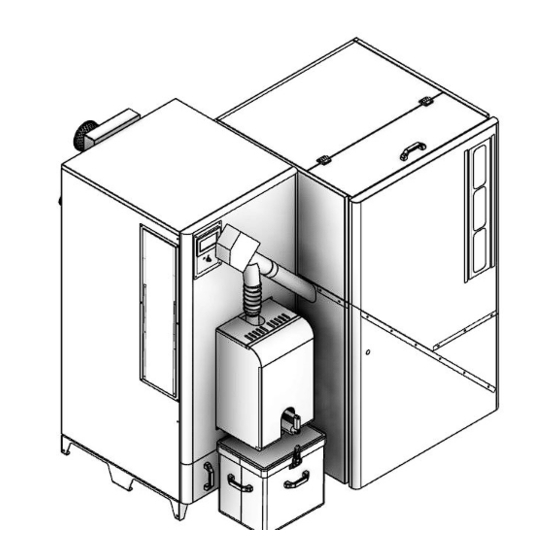
Page 15: Technical Specification
6. TECHNICAL SPECIFICATION 6.1 Main Parts... - Page 16 Touch Panel Ceramic Igniter Safety Limit Thermostat, STB Vacuum Fan Main Auger Flue Exit Burner Limit Thermostat Boiler Body Ash Box Pressure Safety Valve Fuel Silo Handle Filling & Discharge Pellet Silo Hot Water Outlet Burner Return Water Inlet Photocell Ash Discharge Motor...
-
Page 17: Boiler Specifications
6.2 Boiler Specifications BOILER TYPE TECHNICAL SPECIFICATION OF CARIA Unit BOILERS CP-12 CP-23 CP-40 CP-60 CP-80 CP-100 CP-150 12 - 3,6 23 - 6,9 40 - 12 60 - 18 80 - 24 100 - 30 150 - 45 Nominal-Minimum Heat Output kcal/h 10.320 - 3.096 19.780 - 5.934... -
Page 18: Fuel Specification
6.3 Fuel Specification CAUTION: DO NOT USE CHEMICALS OR FLUID TO START THE FIRE CAUTION: DO NOT BURN GARBAGE, GASOLINE, NAPHTA, ENGINE OIL OR OTHER INOPPROPRIATE MATERIALS, BURN WOOD PELLET ONLY CARIA boilers can be fired with high quality wood pellet; Ø6 mm x 30 mm long, with moisture level less than 10%. -
Page 19: Operating Principles
6.4 Operating Principles The boilers have been designed to heat hot water and must be connected to a heating plant and/or a domestic hot water plant within the limits of its performance and output. The boilers have a maximum outlet temperature of 90°C (set point is max. 80°C) and a maximum allowable operation pressure of 3 bar gauge. - Page 20 Ø An optional pressure sensor on the boiler flue gas outlet chamber monitors the system pressure on the boiler gas side, together with the fan speed. Ø If there is either insufficient or no combustion in the burner head, a flame detection photo resistor stops the fuel supply.
-
Page 21: Installation
7. INSTALLATION 7.1 Boiler Placement All installation, assembly and maintenance work must be carried out exclusively by fully trained, professionally qualified personnel and must conform with this manual and the local codes and requirements of the authority having jurisdiction, or in the absence of such requirements, apply to the EEC directives and European norms (EN). This boiler must be installed in accordance with the rules in force and only in a well ventilated and frost-free spaces, indoor but other than living areas. - Page 22 The boiler placement must be set on a non-combustible, such as concrete, tile, stone, and marble floor It is recommended that the boiler be placed on masonry blocks if space permits, to allow easier fueling and to keep the boiler above any water in the basement. These blocks should extend approximately 25 mm (1”) on all sides of the boiler for support and stability.
- Page 23 To assemble the tank, follow the specific instructions provided with the product. Insert the main auger to the silo properly. It should be placed to the bottom box of the silo completely. Pull up the pellet silo to the boiler by aligning the auger to the burner feeding line. Connect the plastic tube between the auger and the burner The installation room of the Caria boilers must comply with the Technical Standards and with the national and local legislation in force and equipped with suitably sized ventilation openings.
-
Page 24: Hydraulic Connections
7.2 Hydraulic Connections Boiler return water temperature must be always above 55 °C otherwise the guarantee will be void. Below diagram can be a good solution which is already proven. LEGENDS: A Pellet Boiler 5 Ball Valve B Buffer Tank 6 Pressure Regulator C Load (Anti-condensation) Valve Groupr 7 Load Valve... - Page 25 CARIA PELLET BOILER'S HYDRAULIC ITEM RECOMMENDATIONS BOILER CAPACITY SPECIFICATION 12 kW 23 kW 40 kW 60 kW Pipe : 1" Flow : 516 l/h Pipe : 1" Flow : 989 l/h Pipe : 1 1/2" Flow : 1720 l/h Pipe : 1 1/2" Flow : 2580 l/h Boiler Water Feed and Velocity : 0.3 m/sec Velocity : 0.45 m/sec...
-
Page 26: Chimney Connection
BOILER WATER AND MAKE UP WATER FOR HOT WATER BOILERS According to EN 12953-10:2003 (Shell boilers: Requirements for feed water quality) Parameter Unit Make up Boiler Water Boiler water Operating pressure Total range Appearance Clear, free from suspended solids, no stable foam Direct conductivity at 25 °C μS/cm <... - Page 27 If there is are local codes or norms for solid fuel chimney, please obey those rules. If there are no local norms, please refer to EN 13384. Below figures are given for a quick reference and these values can vary according to geographic conditions so below figures cannot guarantee a proper operation.
-
Page 28: Boiler Room Ventilation
7.4 Boiler Room Ventilation The boiler must be installed in accordance with the rules in force, only in a well-ventilated and frost free space, indoor but except the living areas. Control the ventilation openings are adequate or not. Told to customer, never obstruct the ventilation openings to the boiler room for a safe and efficient operation. -
Page 29: Power Supply And Polarity
7.5 Power Supply and Polarity Variation of the electrical power supply shall not prohibit the use of the burner or lead to a dangerous situation. Loss of power supply, extremely high voltage peaks or exceptionally low voltage supply to the burner shall not cause bad combustion, back burning or smoke passing out through the pellet burner. - Page 30 Press Menu button to go to the "Boiler Settings" and then “Calibration” submenu. If you are using your burner for the first time, then you should use “Screw filling” option for an accurate calibration. Only after this filling process you can go for “Calibration” by pressing on it. For the first commissioning, you should be sure auger pipe is filled full of the pellet.
- Page 31 If you don’t make any selection the default value of fuel type is defined as “EN plus A1- A2”.To change the fuel type, press “Service Settings” from main menu and enter the password as “1000” and check if it is selected like that or not.
- Page 32 Note: The calibration procedure should be repeated whether the pellet type, size, supplier changed or if you notice a performance drop CONTROL OF THE BOILER & BURNER. Please open the boiler top cover and control all the tabulators are in place and present. Run the boiler from main switch and measure the turbulator vertical movement height.
-
Page 33: Control System
9. CONTROL SYSTEM 9.1 Controller 1 Control panel with display allows selecting and setting all the functional elements of the system on the display, such as operating modes, parameters, etc. 2 CPU control regulates the burner and control heating system with Fuzzy logic and PID control system. 3 Safety thermostat (STB) The thermal safety thermostat turns off the boiler when the water temperature exceeds the limit (between 94 and 100 °... -
Page 34: Touch Panel
9.2 Touch Panel Exit a chosen Menu Return back to Quick access to Menu information Select technical position or cancel a main screen menus concerning the menu (password parameter setting selected Menu needs) position 1-Mode of regulator operation: FIRING UP, OPEARTION, SUPERVISION, BURNING OFF, STANDSTILL 2-Preset boiler temperature 3-Measured boiler temperature 4-Key to enter “Menu”... - Page 35 10-Field of functions, which modify preset boiler temperature-meaning of the symbols: Opening of room thermostat contacts – preset room temperature has been reached Of preset boiler temperature for active time intervals Increase of preset boiler temperature for the time of HUW container filling Increase of preset boiler temperature by mixer circuit Increase of preset temperature for buffer loading Both, left and right windows may display different information.
-
Page 36: Main Menu Structure
9.3 Main Menu Structure The “Menu” icon should be in the middle of the screen. (e.g. in the figure) If the interested icon is not present on the screen: - Touch the any side of screen; the icons scroll, and the other available icons are displayed. - Page 37 Preset Boiler Temperature Weather Control the Boiler Select Only with external probe Boiler Heating Curve Curve Shift Boiler Settings Night Time for Boiler Max power blow-in output Max power feeder operation Output Modulation Average power blow-in output Average power feeder operation Min power blow-in output...
- Page 38 Min power feeder operation Boiler hysteresis Hk-Start Output Modulation Boiler hysteresis Hk-End Boiler Settings Alarm Level Calibraton HUW preset temperature HUW pump mode HUW Settings HUW cont. hysteresis HUW disinfection...
- Page 39 HUW Settings Night time decrease Winter/Summer Mode Preset mixer 1 Temperature Mixer 1 room therm. Mixer 1 weather control Mixer 1 Settings Heating curve mixer 1 Curve translation Mixer 1 night time decrease General Settings Clock Adjustment...
- Page 40 Date Adjustment Screen brightness Adjustment General Settings Sound Adjustment Language Select Software update Wifi settings Scroll and change the Manual Control status(On/Off) Alarms Scroll the pages...
-
Page 41: Service Menu Structure
9.4 Service Menu Structure * unavailable if no adequate sensor or additional module is connected or the parameter is hidden. ** only TOUCH version 9.5 Setting the Parameters You should adjust the parameters of the panel according to the system you build. Using a buffer tank;... - Page 42 · When the “upper buffer tank temperature” reaches “Preset buffer temperature + Hysteresis end loading” and the difference between upper and lower buffer tank temperatures is less than “Delta T” the controller goes to burning off mode. Stops pellet feeding. Waits “Load extension” minutes and then stops the pump. Using a HUW tank;...
- Page 43 Set parameter Weather cont. Mixer to on. Select weather curve as per point. · Automatic correction of room temperature is carried out in accordance with the following formula: Correction = (Preset room temperature - measured room temperature) x room temperature coefficient /10 Example.
-
Page 44: Timer Schedule (Night Time Function)
Guidelines for selection of appropriate heating curve: - If the outdoor temperature drops, and the room temperature increases, the selected heating curve value is too high, - If the outdoor temperature drops, and the room temperature drops as well, the selected heating curve value is too low, - if during frosty weather the room temperature is proper, but when it gets warmer - it is too low, it is recommended to increase the Curve translation and to select a lower heating curve,... -
Page 45: Function Of Protecting Pumps Against Stagnation
After your selection, next screen will show up as above. Here you can make a working schedule for your boiler and assign a temperature value which specify how many degrees (°C) will decrease. A quick reminding; boiler has specific max and min temperature values and boiler temperature can be set only between this allowable interval. Therefore, if Tset.-Tdecrease.<Tmin the boiler will just stop or go to burning-off. -
Page 46: Electrical Connections
9.9 Electrical Connections 9.9.1 Main Control Unit (Module A) -
Page 47: Extension Unit (Module B)
CPU: Control Unit BP: Boiler Pump or Loading Pump (**) FU: Fuse DH: Domestic Water Pump (**) IG: Ignitor PM: Mix System Pump (**) LM: Grate Servo Motor SM: Mix Valve Servo Motor (**) FH: Loading Auger FH: Pellet Loading Screw Motor FL: Buner Grate Cleaning Motor L N PE: Power Supply 230V~50Hz FA: Fan... -
Page 48: Adding Outside Weather Sensor
9.9.3 Adding Outside Weather Sensor The regulator cooperates only with a weather sensor of the CT4-P type. The sensor should be installed on the coldest wall of the building; usually this is the northern wall, under a roof. The sensor should not be exposed to direct sunlight and rain. - Page 49 Reserve boiler control is switched off upon setting the H-output function to the reserve boiler. · Menu → Service Settings → H-output → Reserve Boiler The reserve boiler is switched on when there is no voltage on terminals 46-47. The reserve boiler is switched off when there is voltage on terminals 46-47.
-
Page 50: Start-Up
10. START-UP Make sure fuel is present in the tank and tank hatch is closed. Any time upon filling fuel tank, press and hold pressed current fuel level value. Following prompt appears: "Set fuel level at 100% Once selected and confirmed YES, fuel level is set at 100%. Now boiler may be switched on. -
Page 51: Alarm Codes & Troubleshooting
11. ALARM CODES & TROUBLESHOOTING ALARM 1 – Maximum Boiler Temperature Exceeded When the boiler temperature exceeds “boiler cooling temperature” set value (93°C as default value) the boilers give the alarm and starts cooling mode. Runs all the connected pumps until the temperature set points are reached in the related pumps zone (HUW up to set temperature, Buffer Tank up to 105°C, if floor heating enabled until set temperature else until boiler cooled with central heating pump) ALARM 2 –... - Page 52 pellet feeding is to less according to original figures, please control the screw inlet by opening the small cover on the screw side, down part of pellet silo. If you unscrew only the down screw + unscrew the top screw a little and then turn the small cover to up position, cleaning will be easier.
- Page 53 ALARM 11 – STB is disabled. Manuel reset is needed when boiler temperature ≤ 65 °C Safety limit thermostat is on after state ≥100 °C it stops fan and feeding and give Alarm 11. It should be manually reset from limit thermostat swich. ALARM 12 –...
-
Page 54: Connecting Your Boiler To Internet
12. CONNECTING YOUR BOILER TO INTERNET EcoNET enables boiler operation remote control via Internet or a local network. User can remotely monitor operation of the boiler and modify operation parameters of the boiler controller with the use of a tablet or mobile phone. Essential features of the module: ecoNET integrated WWW server enabling remote control of operation of the boiler within a local network without Internet access,... - Page 55 If you will connect Econet via wireless network you need to enter the SSID, Encryption Method and password. From the information menu you can see the connection, the signal strength and IP address of your controller. WWW server incorporated in ecoNET300 module enables remote management of boiler operation on LAN local network without any access to the Internet.
- Page 56 LOGGING INTO ECO NET ACCOUNT VIA INTERNET: EcoNET300 internet module cooperates with external server which is available under www.econet24.com. This provides access to the boiler controller via Internet. In order to log into an account on an external server, enter www.econet24.com into an address field of the web browser.
- Page 57 In a form field: Regulator not available, try other UID or check if regulator is connected to the Internet ). UTD number of boiler controller is required (in case of improper number or a lack on Internet connection), a following command will be displayed Regulator not available, try other UID or check if regulator is connected to the Internet).
-
Page 58: Updating Firmware
13. UPDATING FIRMWARE To upgrade the TOUCH version software, use micro SD memory card or the ecoLINK II interface. In this section, software upgrade in the TOUCH version using memory card is described. Note: software may be upgraded by authorized personnel only. All electric shock preventive measures must be applied! To upgrade the software, disconnect power supply of the regulator and remove ecoTOUCH control panel from the regulator housing. - Page 59 3 - You should check the slot for the SD card and insert in it properly. 4- After the third step, you will see Update screen from panel. On this screen, there are 2 options “Update A module” and “Update panel” which are related to controller and panel respectively. It is highly recommended that you should start with “Update a module”...
-
Page 60: Maintenance & Service
14. MAINTENANCE & SERVICE Warning For safety reasons, all cleaning and maintenance operations MUST be carried out with the appliance cold and wearing suitable Personal Protective Equipment. If a vacuum cleaner is used, it must also be suitable for vacuuming even hot ash. Warning Do not open any part on the boiler or burner when the system is running. - Page 61 Before starting maintenance and boiler cleaning: · switch off the boiler, deactivate the control panel by pressing the button. · After at least 60 minutes from the extinguishing of the flame, check that it is possible to disconnect the power supply and turn the main system switch to "OFF". Wait until all parts have cooled down further.
- Page 62 · lift and extract, with suitable equipment, the lever / turbulator unit (2). - clean the turbulators, the smoke pipes and the combustion chamber with a brush and the brush supplied with the boiler. · Disconnect the hose and all the electrical connections (e.g.: connector between burner and auger, photocell, heater) ·...
- Page 63 · take out the ash box, and discharge the accumulated ashes, remove the lower part of casing and open the ash door of the boiler. · clean compartment with suitable equipment (e.g. brush, vacuum cleaner)
- Page 64 · After cleaning, reassemble, in the correct position, all the parts previously disassembled by proceeding in reverse order to what has been described and restore the electrical connections of all the components. · Open the previously closed boiler flow and return valves. ·...
- Page 65 Chimney is also very important part of the heating system. You must have always negative pressure ( -2 / -8 Pa) when the boiler fan is not running. Positive pressure can carry back the hot poisonous flue gases to boiler house. Too much negative pressure will also cause problem.
-
Page 66: Disposal Of The Appliance (European Directive 2012/19 / Eu)
15. DISPOSAL OF THE APPLIANCE (EUROPEAN DIRECTIVE 2012/19 / EU) IT IS FORBIDDEN dispose of the product together with urban waste. For Caria CP-12, 23 At the end of their life, boilers and electrical and electronic equipment from private households must not be disposed of with normal mixed urban waste, but must be disposed of, in accordance with the law, based on directives 2012/19 / EU and Legislative Decree . -
Page 67: Commissioning Form
16. COMMISSIONING FORM Konya Yolu 29. Km Oğulbey Mah. Kumludere Cad. No:4 06830 GOLBASI/ANKARA Tel: +90 (312) 615 51 11 Fax: +90 (312) 615 50 56 http://www.arikazan.com info@arikazan.com COMMISSIONED DATE: ……. / ……. / ……… COMMISSIONED BY: NAME: TEL: INITIAL SET VALUES Fuel type: Calibration Weight: ……………... -
Page 68: Guarantee Certificate
No:4 06830 GOLBASI/ANKARA Tel: +90 (312) 615 51 11 Fax: +90 (312) 615 50 56 http://www.arikazan.com info@arikazan.com The warranty conditions of each model are attached to the instruction manuals accompanying the product. Tüm modeller için garanti şartları size gelen kullanım kitapçığının içinde verilmiştir.
Need help?
Do you have a question about the CARIA Series and is the answer not in the manual?
Questions and answers