Advertisement
Table of Contents
- 1 Table of Contents
- 2 Introduction
- 3 Warnings
- 4 DECLARATION of CONFORMITY
- 5 Guarantee and Service
- 6 General Specifications
- 7 Operating Principles
- 8 Main Parts
- 9 Installation
- 10 OPERATION and SHUT-DOWN
- 11 Boiler Control Panel
- 12 Maintenance and Servicing
- 13 Spare Parts List
- 14 Boiler Name Plate
- Download this manual
Advertisement
Table of Contents

Subscribe to Our Youtube Channel
Related Manuals for Arikazan Ventum Series


Summary of Contents for Arikazan Ventum Series
- Page 1 KAVAKLIDERE ANKARA TURKEY TEL: +90 312 468 09 11 FAX: +90 312 468 45 96 E-MAIL: ari@tr.net VENTUM SERIES WOOD FIRED GASIFICATION HOT WATER BOILERS VG-20, VG-30, VG-40, VG-60, VG-80, VG-100 OPERATION, USE AND MAINTENANCE MANUAL Rev D: October 2015...
-
Page 2: Table Of Contents
INDEX INTRODUCTION ....................- 2 - WARNINGS ......................- 2 - DECLARATION of CONFORMITY ..............- 5 - GUARANTEE AND SERVICE ................- 6 - GENERAL SPECIFICATIONS ................- 6 - OPERATING PRINCIPLES ................. - 7 - MAIN PARTS ......................- 8 - INSTALLATION .................... -
Page 3: Introduction
INTRODUCTION This manual comprises the information concerning the operation, use and maintenance of VG Model Gasification Type Wood Fired Hot Water Boilers. This manual alone is not sufficient for correct installation, operation and use; installers, services and end user must obey the rules specified in current EN + local norms, EC directives and local codes. - Page 4 If the boiler is heated above 90 °C, do not supply cold water to the system for rapid cool down. It can cause an explosion. Wait the boiler cool down naturally down to 40 °C before any operation. Do not use this appliance if any part has been under water.
- Page 5 A primary loop pump must feed all zones. Each boiler should be connected to a heat storage tank (buffer tank) for proper operation, and the capacity of the buffer tank must be according to local standards. To protect the boiler against low-temperature corrosion and tar accumulation in the boiler, the end-user should assure return temperature does not reach lower than 60°C.
-
Page 6: Declaration Of Conformity
KAVAKLIDERE ANKARA TURKEY CE Konformitätserklärung CE Declaration of Conformity CE Déclaration de conformité Arikazan Makina Sanayi ve Ticaret A.S. - 06800 Ankara Neus Erkären in alleiniger Verantwortung, dass die Heizkessel-Reihe Declare under our sole responsibility that the boiler series Déclarons sous notre seule responsabilité que le serie des chaudieres... -
Page 7: Guarantee And Service
GUARANTEE AND SERVICE Provided that the principles, warnings and standards set out in the operation in this manual and taking into account the national installation regulation of the country (in the absence or of such requirements, they shall be referred to EN norms, directives and codes) are complied with, your boiler shall be under the warranty for a period of 2 (two) years starting from the date of dispatch (from manufacturer) against any faults of material and workmanship. -
Page 8: Operating Principles
OPERATING PRINCIPLES VG boilers have been designed to heat hot water and must be connected to a heating plant and/or a domestic hot water plant within the limits of its performance and output. They are hot water boilers with a maximum outlet temperature of 90 °C and a maximum allowable operation pressure of 3 bar gauge. -
Page 9: Main Parts
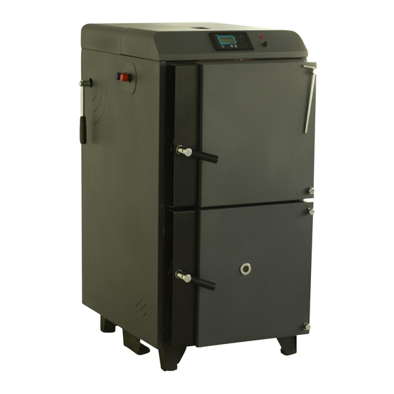
MAIN PARTS Water Inlet/Outlet Main Body Cover Plates Furnace Heat Exchanger Flame Monitoring Tube Cleaning Mechanism Feet Boiler Tubes Upper Door Top Refractory Bottom Door Bottom Refractory Fan Box Control Panel Smoke Box - 8 -... -
Page 10: Installation
INSTALLATION All installation, assembly and maintenance work must be carried out exclusively by fully trained, professionally qualified personnel and must conform with this manual and the local codes and requirements of the authority having jurisdiction, or in the absence of such requirements, apply to the EEC directives and European norms (EN). - Page 11 The choice of the right boiler size, that is its heating output, is a very important condition for economic operation and right function of the boiler. The boiler must be chosen so that its nominal output responds to heat loss of the heated volume. I.
- Page 12 Chimney Height in m Boiler Chimney Inner Diameter in mm Type VG20 VG30 VG40 VG60 10,5 VG80 10,5 VG100 Exact dimensions of flue must be calculated according to local codes. Flue draught is specified in technical parameters. Exhaust pipe must have the outlet into the chimney. If the boiler can not be attached to the chimney directly, the exhaust pipe must be without heating surface and it must rise to the flue.
- Page 13 In order to prevent corrosion special care needed for oxygen infusion to the heating system water side. Possible points for oxygen infusion are from open vented cisterns, negative pressure points on the system and some gas permeable system items like plastic pipes. V.
-
Page 14: Operation And Shut-Down
All the system control and security devices are present and installed according to the current regulations and working properly. Control the boiler gas side seals are not damaged and fixed properly. (boiler front door, burner mounting plates, smoke box, flame monitoring glass) In starting a new installation all the water pipes, boiler and all the other heating system items must be flushed and free from deposits. - Page 15 Some Hints for a trouble free operation; Do not block the flame nozzle complete when you are filling the wood logs. If you have a bridge problem and the wood logs are stay at top than try to use half length wood logs, eg: for 50 cm combustion chamber use 25 cm logs.
-
Page 16: Boiler Control Panel
There will be some red hot fuel for reigniting, so after AL1 you can fill some more fuel and the left ambers will be enough for ignition. BOILER CONTROL PANEL Ventum series uses ecoMax 200 control boards. It offers an easy and efficiency usage. Legend: 1. Menu item change button 2. - Page 17 Legend: 1. preset boiler or hot utility water tank temperature, or preset temperature of emission, 2. measured temperature of boiler, hot utility water tank, or stack gas (emission) temperature, 3. Arrow sign 4. SUMMER – hot utility water mode symbol 5.
- Page 18 2 – mains switch in the regulator, 3 – protective terminals PE, 4 – metal enclosure of the regulator, MAINS – mains lead, STB – safety temperature limiter, - 17 -...
- Page 19 Enabling the SUMMER function In order to enable the SUMMER function, which allows to heat the hot utility water tank in the summer without the need of warming the central heating system, set the parameter hot utility water mode = 3. ...
- Page 20 Troubleshooting Signs of a fault Hints 1. The display is blank despite connection to the The main electric supply is off. Control the fuses supply network. whether the hot utility water tank is filled at the time and the preset hot utility water temperature is higher than the boiler preset temperature;...
-
Page 21: Maintenance And Servicing
MAINTENANCE AND SERVICING Wait up to all the fuel finished in the boiler and the boiler temperature is less than 40 °C. Please stop all the system from control panel, disconnect the power supply and always wait until all the parts are cooled down before any cleaning and servicing operations. - Page 22 And run the system. Again min. once a year call your authorized service for checking the combustion parameters, security and operational devices. Do not alter the security devices preset values If the boiler door ceramic fiber packing gas seals in any part of the boiler is not proper and if there is a gas leak out of boiler, please call an authorized service for repair or replacement.
-
Page 23: Spare Parts List
SPARE PARTS LIST Upper Front Door Lower Front Door Heat Exchanger Group Tube Cleaning Group Fan Group Electrical Panel Back Door Cover Plates Refractories Air Regulation Clape - 22 -... - Page 24 Part Number Part Name Quantity per Boiler Door Gasket Door Hinge Group Door Handle Group Bacalite Arm Hinge Fastening Arm Door Lock Door Lock Pin - 23 -...
- Page 25 Part Number Part Name Quantity per Boiler Door Gasget Flame Monitoring Glass Monitoring Glass Cap Ash Rake Ash Box - 24 -...
- Page 26 Part Number Part Name Quantity per Boiler Heat Exchanger Mechanical Thermos. Valve Blind Plug Gasket - 25 -...
- Page 27 Part Number Part Name Quantity per Boiler Turbulators 6 to 12 Turbulator Shaft 1 to 2 Turbulator Cleaning Shaft Cleaning Arm Cleaning Arm Handle Turbulator Shaft Lifting Arm Turbulator Shaft Bearing 2 to 4 4.11 Top Door 4.14 Top Door Ceramic Isolation 4.15 Tube Cleaning Brush - 26 -...
- Page 28 Part Number Part Name Quantity per Boiler Propeller Fan Cover Box Fan Gasget - 27 -...
- Page 29 Part Number Part Name Quantity per Boiler Controller Limit Thermostat Flue Gas Temperature Sensor Boiler Temperature Sensor Sanitary Water Temp. Sensor Lamb Panel Case 6.11 Capacitor 6.12 Crimp-on Snap Connector 6.13 Door Switch - 28 -...
- Page 30 Part Number Part Name Quantity per Boiler Back Door Back Door Insulation Board - 29 -...
- Page 31 Part Number Part Name Quantity per Boiler Top Front Cover Plate Top Back Cover Plate Left Cover Plate Right Cover Plate Upper Front Door Cover Plate Lower Front Door Cover Plate Rear Cover Plate Heat Exchanger Cover Plate 8.13-8.14 Connection Sockets - 30 -...
- Page 32 Part Number Part Name Quantity per Boiler Upper Refractories Upper Middle Refractories Ceramic Fiber Isolation Middle Refractories Ceramic Fiber Isolation Bottom Refractories - 31 -...
-
Page 33: Boiler Name Plate
BOILER NAME PLATE COMMISIONING DATE : …… / ……. / ……… COMMISIONED BY : NAME : TEL : INTIAL SET VALUES Fuel type: System pressure: …………… mbar - 32 -... - Page 34 APPENDIX-1 - 33 -...
- Page 35 - 34 -...
- Page 36 APPENDIX-2 BOILER TYPE TECHNICAL SPECIFICATION OF VENTUM TYPE WOOD GASIFICATION Unit BOILERS VG20 VG30 VG40 VG60 VG80 VG100 Nominal Heat Output kcal/h 17.200 25.800 34.400 51.600 68800 86000 Minimum Heat Output N.A / equal to Nomial Heat Output Direct Efficiency 90,1 90,4 91,2...
- Page 37 ØD2 ØD3 ØD2 ØD4 - 36 -...
- Page 38 GUARANTEE CERTIFICATE GARANTİ SERTİFİKASI BÜYÜKELÇI SOK. NO:9 06700 KAVAKLIDERE ANKARA TURKEY TEL: +90 312 468 09 11 FAX: +90 312 468 45 96 E-MAIL: ari@tr.net The warranty conditions of each model, are attachted to the instruction manuals accompanying the product. Tüm modeller için garanti şartları...
Need help?
Do you have a question about the Ventum Series and is the answer not in the manual?
Questions and answers