Table of Contents
Troubleshooting

Related Manuals for Tuttnauer TIVA8-1ML

Summary of Contents for Tuttnauer TIVA8-1ML
- Page 1 GLASSWARE WASHER TIVA8 - 1ML TIVA8 - WD - 1ML INSTRUCTIONS FOR USE Original instructions Before starting to operate with code MAN205-0746001EN - Rev. 00 the glassware washer, read Edit. 05-2021 these instructions for use Language: English...
- Page 2 Tel. +31 (0) 765 423 510 - +31 (0) 765 423 540 E-mail: info@tuttnauer.nl Models covered by the manual: TIVA8-1ML | TIVA8-X-1ML | TIVA8-XE-1ML TIVA8-WD-1ML | TIVA8-WD-XE-1ML WARNING It is strictly forbidden to use the machine before having read and understood this manual.
-
Page 3: Table Of Contents
Operative Instructions Content 6.4 Starting the machine..... . 25 6.4.1 Before starting the program ... . . 25 1 Symbols used in the manual . -
Page 4: Symbols Used In The Manual
Operative Instructions 1 Symbols used in the manual WARNING: The manufacturer also declines any and all liability for failure to comply Actions of particular importance or of potential risk and with the safety and prevention regulations danger are highlighted in the manual with a symbol provided by the legislation and the provisions whose meaning is set out below. -
Page 5: Field Of Application
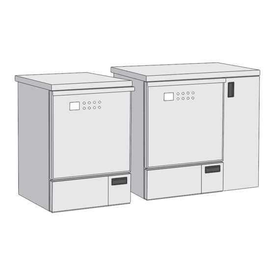
Operative Instructions 2.2 Label specifications - The standard model is the classic model of glasswasher, can be installed under the counter Each glasswasher is equipped with 2 identification where appropriate space is already provided. labels (for positions see Fig. 2.1 and 2.2). The following - The model with side panel differs from the standard table shows the symbols used on the identification model for its dimensions because of its side panel... -
Page 6: Warranty
Operative Instructions 2.3 Warranty - Malfunctions due to voltage fluctuations or hydraulic pressure fluctuations or other external causes The manufacturer warrants the newly manufactured - If the damages caused by bumps and falls product for 12 (twelve) months from the date of the - If non original spare parts are used. -
Page 7: Product Analysis
Operative Instructions The user must also be able to perform these actions: • be operational at a temperature between 5 and 40°C - Machine commissioning and operation; (41 and 104°F); - Loading and unloading of the material being washed • operate in an environment with a maximum humidity on the racks;... -
Page 8: Technical Data
Operative Instructions The manufacturer therefore recommends that: Max dBA noise during <56 dB (A) - the water used in the pre-rinse and washing stage wash phases should be of drinking quality according to the Max dBA noise during <61 dB (A) “Guidelines for drinking-water quality, 4th edition”... -
Page 9: Accessories
Operative Instructions 2.7 Accessories The machine leaves the factory without any accessory or rack. The user must request the most suitable accessory or rack from the manufacturer. Figures below shows some examples of the most common use accessories. Fig. 3a Fig. - Page 10 Operative Instructions Fig. 3h Fig. 3d Fig. 3i Fig. 3l Fig. 3e Fig. 3m Fig. 3n Fig. 3f Fig. 3g Fig. 3o...
-
Page 11: Safety And Prevention
Operative Instructions 3 Safety and prevention The operator in charge must be instructed on the risks deriving from accidents, on the devices prepared for the safety of the operator and on the accident-prevention rules provided by the legislation of the country of use of the machine. -
Page 12: Operator Obligations
Operative Instructions • The electrical and water connections can only be • Do not lean on the door and do not use it as a step. made by specialised technicians, paying particular • The machine during its work cycle could reach a attention not to crush the power supply cable and the temperature of 95°C (203°F);... -
Page 13: Handling
Operative Instructions • At the end of the maintenance and repair operations, and position cannot constitute danger. before restarting the machine, make sure that the Therefore, remove the ropes and unload using the work is completed, the safety devices reactivated and same equipment and methods used for loading. -
Page 14: Storage
Operative Instructions - Remove the “hat” container, extracting it from the If this is not provided, dispose of the packaging top (Fig. 4b). materials: cardboard, polystyrene and other, separated - Handle the machine with appropriate trolley. Lock the by single material, sending them to the most machine on the trolley with a sturdy belt (Fig. -
Page 15: Built-In Installation
Operative Instructions WARNING: The use of unsuitable parts, The built-in machine can be inserted under a and/or the implementation of installation continuous worktop or under the sink’s drip surface. procedures other than those shown on the The recess niche must have a minimum space as shown installation diagram, will immediately void in Fig. -
Page 16: Electrical Connection
Operative Instructions Damaged fuses must be replaced by connected to the public electricity grid. authorised personnel. (for the value and size The high-frequency (HF) energy emissions of of the fuses see annexes 11.9). the machine are so small that interferences with electrotechnical equipment in the immediate vicinity are not likely. - Page 17 Operative Instructions The special washing machine is standard prepared for - If present, install the Disconnector CA while connection to cold and hot water. Connect the flow maintaining a clear area of 150 mm (6") around the pipes to the shut-off valves for cold and hot water. valve (For more information see the Installation Plan).
-
Page 18: Models With Built-In Water Softener
Operative Instructions 5.3.1 Models with built-in water softener the solenoid valves to close. The integrated function of the softener is used to 5.4 Connection of the drain trap reduce the amount of limescale contained in the The machine is equipped with a built-in drain trap incoming water. -
Page 19: Drain Connection
Operative Instructions Fig. 8 Water and drain system (Fig. 8): 5.5 Filters, spray arms and regeneration salt A) Floor drain connection. B) Wall drain connection. 5.5.1 Filters 1) Hose connection waste water. 2) Hose connection capacitor discharge machine. 3) Minimum connection point 100 mm (3.9"). Maximum connection point 600 mm (23.6"). -
Page 20: Spray Arms
Operative Instructions 5.5.2 Spray arms 5.5.3 Regeneration salt The two spray arms are supplied loose to avoid possible The glasswasher is supplied with regeneration salt breakage during transport. Place the two spray arms which will feed the device automatically during the (lower and upper) in their seats and tighten them to regeneration process. -
Page 21: Automatic Regeneration
Operative Instructions 5.6.1 Refill procedure Following the instructions in the start-up paragraph, start the «Prewash» program. 1) Set up a new tank with the chemical. 2) Remove the suction lance from the exhausted tank. Ö 3) Insert the suction lance in the new tank. ATTENTION: After the salt refill action, the 4) With the door open, press and hold key 1 to refill first wash cycles may fail. -
Page 22: Using The Machine
Operative Instructions 6 Using the machine chemicals’ labels. The manufacturer recommends a method for inventory management (first in - first out). Before starting the machine, the operator in charge The glasswasher can use up to four products for dosing must have read and understood this whole manual, liquids. -
Page 23: Loading The Chemicals
Operative Instructions 6.1.1 Loading the chemicals - small glassware: lids, spatulas, magnetic laboratory stirrers, stoppers; When changing the tanks chemicals, it is required to - other glassware such as petri dishes, funnels, pieces perform the manual filling of the hydraulic circuit. This of tubing/cable, etc... -
Page 24: Preparing The Load
Operative Instructions 6.2.2 Preparing the load - Components with special geometries must be - The glassware to be washed must be placed on the arranged so as to allow the water to flow out. relative racks, making sure that they do not overlap - Introduce only suitable steel instruments, resistant to one another. -
Page 25: Treatment Of Glassware
Operative Instructions Wide-necked glassware • Drying: Sufficient drying reduces the risk of corrosion caused by the residual humidity on the load (not Wide-necked glassware (such as beakers, Erlenmeyer available for models without drying system). flasks and Petri dishes) or cylindrical glassware (such as test tubes) must be washed and rinsed both internally 6.4 Starting the machine and externally. -
Page 26: Program End
Operative Instructions Ö Program execution IMPORTANT: In the version without drying system, the glassware must NOT be left Once the program has started, its progress can be inside the machine, at the end of the cycle, followed on the display. The display shows the program wet, for longer than 5 minutes. -
Page 27: Control Panel
Operative Instructions 7 Control Panel The control panel consists of 8 keys and a 3.5 inch LCD display. All keys, except key "3", are multi-function, depending on the action being performed in a specified state of the device. Fig. 13 6) Prg Here below the description of the control panel standard (STD) and special (SPC) functions. -
Page 28: Display
Operative Instructions 7.2 Display temperature detectable by the two probes must not differ from each other by more than 2°C (36°F); The LCD display shows the status of the machine. 10) Time for which the device should maintain the set The images show the various phases and the current temperature (see 12);... -
Page 29: Display Screens
Operative Instructions For more information on bluethooth, see paragraph 8.2. 7.2.3 Display screens After starting the machine, following the instructions in chapter «6.4 Starting the machine», the display will show the images indicating step-by-step the operations in progress. 1) Once the machine has started, the display shows the screen indicating door open and the invitation to insert the rack with the instruments to be washed. -
Page 30: Program 8 Standard
Operative Instructions 7.2.4 Program 8 Standard Phase 3 8) At the end of the prewash phase, the water is Phase 1 automatically discharged. 5) The machine starts the automatic work cycle and discharges any residual water present in the chamber. Fig. - Page 31 Operative Instructions 14) Rinse phase begins: the machine will rise the water 11) When the water reaches the 35°C (95°F), the peristaltic pump 1 will dose the detergent. temperature to the presetted value and will keep it for the presetted time. Fig.
- Page 32 Operative Instructions Phase 8 17) Self-loading of deionized water. During the self- loading phase the chamber will be filled. Fig. 16.21 Phase 10 20) Dry phase begins: hot air is blown inside the Fig. 16.18 chamber at a preset temperature and kept for 18) Rinse phase begins: the machine will rinse the the preset time.
-
Page 33: Alarm Messages
Operative Instructions If, for any reason, it is necessary to interrupt the cycle, To access the settings menu the procedure is as follows: simply hold down the RESET key for a few seconds until Open door -> PRG key for 5 seconds -> If the user and an audible alarm (buzzer) is heard and an alarm screen password are enabled, insert user password. -
Page 34: Usb Key Management
Operative Instructions Language” setting and select the desired language from those available: 1=IT, 2=EN, 3=DEU, 4=FR, 5=SP, 6=POR, 7=SW. 7.2.9 USB key management: When the USB key is hooked up in the machine, the following message appears after a few seconds: Fig. -
Page 35: Bluethooth
Operative Instructions Ö The software comes with a free one week Before maintenance, start a program to wash the (7 days) trial period, at the end of the trial washing chamber. period you must contact your dealer or 9.1.2 Cleaning products distributor to enter the activation code to Clean the outside of the machine with products continue using the software. -
Page 36: Clean The Filters
Operative Instructions 9.2.1 Clean the filters Proceed as follows to clean the filters in the wash chamber: 1) Open the door and remove the load rack. Warning: Very hot surfaces Risk of injury: Be careful with sharp and pointed objects, which are withheld in the racks. -
Page 37: Spare Parts
Operative Instructions machine to a suitable and authorised collection centre. The electrical and electronic devices to be disposed of contain reusable materials. They also contain components harmful for the environment, but necessary for the correct operation and safety of the equipment. If they are not disposed of correctly or are disposed of as household waste, these components can damage human health and the environment. -
Page 38: Annexes
Operative Instructions 11 Annexes 11.1 Menu parameter table Factory Parameter Name Description Default GENERAL Turns the buzzer on or off at the end of End cycle buzzer 0=OFF 1=ON a cycle Warning alarm Turns the buzzer on or off when an 0=OFF 1=ON buzzer... - Page 39 Operative Instructions Factory Parameter Name Description Default Selects the program to be combined Program button 2 with button 2 Selects the program to be combined Program button 3 with button 3 Selects the desired language for the Printer language ENGLISH printer Enables or disables the drying stage Drying enable...
- Page 40 Operative Instructions Factory Parameter Name Description Default Hot water filling Sets the timer for the pump in the 1000 time absence of the flowmeter count seconds Deionized water Enables or disables the deionized water 0=OFF 1=ON flowmeter flowmeter Deionized water Sets the timer for the pump in the 1000 filling time...
- Page 41 Operative Instructions Factory Parameter Name Description Default Number of cycles performed with program... Number of cycles performed with Program cycles 40 program 40 USER PIN To set the user password, press the Pin User 1 RESET key and enter the 6 desired numbers Pin User 2 Pin User 20...
-
Page 42: Menu Structure
Operative Instructions 11.2 Menu structure S����-�� ���� (����� ��� �� �������) P���� P�� (5 �.) �� ����� �� ��� ���� ���� G������ End cycle buzzer Program bu�on 1 Warning alarm buzzer Program bu�on 2 Bu�ons noise Program bu�on 3 Device 1 Printer language Device 2 Drying enable... -
Page 43: Procedure For Password Change
Operative Instructions 11.3 Procedure for password change D��� O��� P���� S���� (3 �.) P���� D��� �� ���� Select User Y�� User Blocked? N� P���� D��� �� ���� Press Start to confirm P���� D��� �� ���� Enter old password P���� D��� ��... -
Page 44: Super User
Operative Instructions 11.4 Procedure for user password setup for the super user S����-�� ���� (����� ��� �� �������) P���� P�� (5 �.) P���� D��� Insert Super User �� ���� password (max 3 a�empts) N� valid? Y�� See password change Y�� is expired or procedure first access? -
Page 45: Procedure For Super User Password Change
Operative Instructions 11.5 Procedure for super user password change S����-�� ���� D��� O��� (����� ��� �� �������) P���� P�� (5 �.) P���� D��� Insert Super User �� ���� password (max 3 a�empts) N� Password See password change expired? procedure Y�� P����... -
Page 46: Alarm Table
Operative Instructions 11.6 Alarm table ALARM DESCRIPTION ACTION 1- Press RESET EEPROM ALARM Firmware installed successfully. 2- Install new dataset A blackout occurred during cycle BLACKOUT Press RESET execution and the program was stopped. The door is open or unlocked. Press RESET DOOR OPEN Close the door. - Page 47 Operative Instructions ALARM DESCRIPTION ACTION A too high temperature was detected Press RESET PREWASH TEMPERAT during the prewash phase. If it persists, call the technician. A too high temperature was detected Press RESET CHAMBER T.LIMIT inside the chamber. If it persists, call the technician. Press RESET AIR T.LIMIT A too high air temperature was detected.
-
Page 48: Warnings Table
Operative Instructions 11.7 Warnings table WARNING TYPE DESCRIPTION ACTION LIQUID RESERVE Product 1 is in reserve or may be empty. Add the product 1 PRODUCT 1 LIQUID RESERVE Product 2 is in reserve or may be empty. Add the product 2 PRODUCT 2 LIQUID RESERVE Product 3 is in reserve or may be empty. -
Page 49: Fuses
Operative Instructions 11.9 Fuses... -
Page 50: Notes
Operative Instructions NOTES... - Page 51 Operative Instructions...
- Page 52 Tuttnauer Europe b.v. Hoeksteen 11, 4815 PR P.O.B. 7191, 4800 GD Breda The Netherlands Tel. +31 (0) 765 423 510 - +31 (0) 765 423 540 E-mail: info@tuttnauer.nl...
Need help?
Do you have a question about the TIVA8-1ML and is the answer not in the manual?
Questions and answers