Viking DCIH3604 Installation Manual
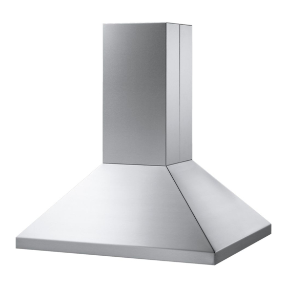
Viking range designer dcih3604 range hood: installation guide
Hide thumbs
Also See for DCIH3604:
- Use & care manual (10 pages) ,
- User manual (44 pages) ,
- Brochure & specs (44 pages)
Advertisement
Quick Links
Advertisement

Related Manuals for Viking DCIH3604


Summary of Contents for Viking DCIH3604
- Page 1 Viking Installation Guide Designer Hoods...
- Page 2 Please Read and Follow! NOTE:...
- Page 3 Please Read and Follow! ” ( 4 0 ” ( 3 0 2 ” ( 5 . ” A (Hood width) ( 6 1 30”W. 29-7/8” (75.9 cm) 36”W. 35-7/8” (91.1 cm) NOTE: * Disregard when using recirculating kits. 460 CFM blower is shipped with hood. NOTE: ( 3 0 ”...
- Page 4 ” m ( 1 6 i n . 7 . 6 ” m ( 1 7 5 . 3 ” ( 9 1 ” m ( 7 6 i n . 30”W. 14-15/16” (37.9 cm) ” m 36”W. 17-15/16” (45.6 cm) ( 8 3 16”...
- Page 5 A (Duct cover width) ” 30”W. 10” (25.4 cm) ( 3 0 33“W. 10” (25.4 cm) 36”W. 12” (30.5 cm) 39“W. 12” (30.5 cm) 42”W. 12” (30.5 cm) 45“W. 12” (30.5 cm) 48”W. 18” (45.7 cm) 51”W. 18” (45.7 cm) B (Hood width) 2 ”...
- Page 6 30”W. 10” (25.4 cm) 1-1/2” 1-1/2” 33“W. 10” (25.4 cm) (3.8 cm) (3.8 cm) 36“W. 12” (30.5 cm) 39“W. 12” (30.5 cm) 42“W. 12” (30.5 cm) 6” (15.2 cm) 45“W. 12” (30.5 cm) 1-1/2” (3.8 cm) 30”W. 14-15/16” (37.9 cm) 33“W.
- Page 7 ” A (Duct cover width) ( 3 0 36”W. 12” (30.5 cm) 42”W. 12” (30.5 cm) 54”W. 18” (45.7 cm) 2 ” ( 5 . B (Hood width) ” 36”W. 35-7/8” (91.1 cm) ( 7 6 42”W. 41-7/8” (106.4 cm) 54”W.
- Page 8 12” (30.5 cm) 36”W. 17-15/16” (45.6 cm) 4-3/4” 42”W. 20-15/16” (53.2 cm) (12.1 cm) 4-3/4” 12” (12.1 cm) (30.5 cm) 15” 120 V (38.1 cm) power 7” (17.8 cm) dia. supply duct location 26-15/16” (68.4 cm) 18” (45.7 cm) 7” 120 V (17.8 cm) power supply...
- Page 9 ” A (Duct cover width) ( 3 0 30”W. 12” (30.5 cm) 36”W. 12” (30.5 cm) 42”W. 12” (30.5 cm) ” 48”W. 20” (50.8 cm) ( 3 3 ( 5 3 ” 2 ” ( 5 . ( 8 3 ”...
- Page 10 5-9/16” 1-1/8” (14.3 cm) (2.9 cm) 5-1/8” (13.0 cm) 30”W. 15-3/4” (40.0 cm) 120 V 36”W. 18-3/4” (47.6 cm) power supply 42”W. 21-3/4” (55.2 cm) 7” (17.8 cm) 11” dia. duct (27.9 cm) location 23-15/16” (60.1 cm) 7-7/8” (20.0 cm) 1-1/8”...
- Page 11 A (Duct cover width) 30”W. 29-7/8” (75.9 cm) 36”W. 35-7/8” (91.1 cm) 42”W. 41-7/8” (106.4 cm) 48”W. 47-7/8” (121.6 cm) 2 ” ( 5 . e l s ” B (Hood width) ( 6 1 30”W. 29-7/8” (75.9 cm) 36”W. 35-7/8”...
- Page 12 18-3/4” (47.6 cm) A (Duct diameter) 4-5/8” 9-1/8” (11.7 cm) VIV300 7” (17.8 cm)/10“ (25.4 cm) (23.2 cm) VIV600 7” (17.8 cm)/10“ (25.4 cm) VIV1200 10” (25.4 cm) 9-3/8” 9-5/8” (23.8 cm) (24.4 cm) Tall Traditional Tall Traditional Ledgeless with Ledge 23-15/16”...
- Page 13 ” ( 3 0 A (Duct cover width) 30”W. 29-7/8” (75.9 cm) 36”W. 35-7/8” (91.1 cm) 42”W. 41-7/8” (106.4 cm) 48”W. 47-7/8” (121.6 cm) B (Hood width) 30”W. 29-7/8” (75.9 cm) ” 36”W. 35-7/8” (91.1 cm) ( 6 1 42”W. 41-7/8”...
- Page 14 5-9/16” (14.3 cm) 1-1/8” (2.9 cm) (13.0 cm) 30”W. 15-3/4” (40.0 cm) 120 V 36”W. 18-3/4” (47.6 cm) power supply 42”W. 21-3/4” (55.2 cm) 7” (17.8 cm) 11” dia. duct (27.9 cm) location 23-15/16” (60.1 cm) 7-7/8” (20.0 cm) 1-1/8” (2.9 cm) 6”...
- Page 15 Roof cap 7” round duct Roof cap 10” round duct Exterior blower 10” round duct Wall cap Duct NOTE: Wall exhaust must be a minimum of 24” (61.0 cm) NOTE: from ground. This may vary depending on local codes and geographic location. 300 or 600 CFM single blower interior-power...
- Page 16 BARE OR GREEN GREEN BLACK WHITE BLACK WHITE NOTE:...
- Page 17 BARE OR GREEN GREEN BLACK WHITE BLACK WHITE NOTE:...
- Page 18 6 ” 1-1/2”x 3/4” Slot for (3.8 cm) x (1.9 cm) wood strip 5/16” wood strip nut driver 5/16” nut driver To install ventillation kit refer to ventillation kit installation instructions. 5/16” nut driver...
- Page 19 BARE OR GREEN WHITE WHITE NOTE: To install ventillation kit refer to ventillation kit installation instructions. GREEN BLACK BLACK...
- Page 20 NOTE:...
-
Page 21: Mounting Options
NOTE: Mounting options: Using duct cover with ceiling mounting bracket. (Option A) To install ventillation kit Using threaded rod for additional support. refer to ventillation kit (Option B) installation instructions. Attaching hood to directly to soffit. (Skip to step 3) NOTE: It is recommended to follow option A or B, however both aren’t necessary. - Page 22 Refer only to features equipped with this unit 2 PRONG MALE CORD INTERNAL EXTERNAL BLOWER BLOWER 2 PRONG FEMALE SOCKET BLOWER NEUTRAL BLOWER LINE 18 GA WHITE 18 GA RED CONTROL PANEL LIGHT NEUTRAL LIGHT LINE 18 GA WHITE 18 GA WHITE LIGHT ASM LIGHT ASM BULB...
Need help?
Do you have a question about the DCIH3604 and is the answer not in the manual?
Questions and answers