
Related Manuals for Aquafine Avant Series


Summary of Contents for Aquafine Avant Series
- Page 1 Avant™ Series Operation and Maintenance User Manual Original Instructions Edition 5 ® Aquafine Corporation 2023 All rights reserved. Printed in Canada. DC650101-05-02...
- Page 2 If you require technical assistance, please contact Aquafine Corporation Technical Support using the contact information below: Telephone: 1-661-257-4770 E-mail: techservice@trojantechnologies.com At the time of publishing, the information within this document is current. Due to continuous improvements, we may have future changes and recommendations which will be sent via product bulletins.
-
Page 3: Table Of Contents
Table of Contents Section 1 Specifications........................7 Section 2 Safety Information ........................ 9 2.1 Use of Hazard Information ......................9 2.2 Precautionary Labels ........................9 2.3 Safety Precautions ........................11 2.4 Safety Features.......................... 14 Section 3 General Information ......................15 3.1 Acceptable Noise Levels...................... - Page 4 Table of Contents 8.2 System Overview Screen ......................50 8.2.1 System Status Information ....................51 8.2.2 Control Mode Screen......................51 8.2.3 Local System Control Buttons ...................53 8.2.4 Remote Control Mode Message..................53 8.3 Lamp Status Screen........................53 8.3.1 Lamp and Driver Information Screen.................54 8.3.2 Lamp and Lamp Driver Information ...................55 8.3.3 Reset a Lamp Driver Fault....................55 8.3.4 Reset Lamp Hours......................55 8.4 Settings Screen ..........................57...
- Page 5 Table of Contents 10.3.5 Control Power Panel ..................... 100 Section 11 Replacement Parts and Accessories ................101 11.1 UV Lamp and Lamp Sleeve ....................101 11.2 UVI Sensor..........................102 11.3 Systems without UVI Sensor....................103 11.4 UVI Sensor..........................104 11.5 Baffle Assembly ........................105 11.6 UV Chamber ..........................
- Page 6 Table of Contents Original Instructions...
-
Page 7: Section 1 Specifications
80 - 250 gpm (352.2 - 1100.8 m /hr) Quartz Maximum Flow Rate* - High Contact Aquafine for Sizing Performance Quartz *Flow Rate at 99% UVT UV Lamp Low pressure, High output (254 nm or 185 nm, with non-validated or... - Page 8 Specifications UVI Sensor Output range 4 to 20 mA current loop (2 wire) Supply Voltage 24 VDC from the Control Power Panel Maximum Operational Temperature 131°F (55°C) Maximum Non Operational 194°F (90°C) Temperature System Regulatory Compliance cULus, CE, UKCA and KC optional Original Instructions...
-
Page 9: Section 2 Safety Information
Section 2 Safety Information Please read this entire manual before operating this equipment. Pay attention to all danger, warning and caution statements in this manual. Failure to do so could result in serious personal injury or damage to the equipment. Make sure that the protection provided by this equipment is not impaired. - Page 10 Safety Information This symbol indicates the components of the system have been exposed to biohazardous waste. This symbol indicates a trained and competent lift operator should be used to move the equipment. This symbol indicates a body crush hazard. People should stay clear from under overhead loads. This symbol indicates surfaces may be slippery and there is a potential fall hazard.
-
Page 11: Safety Precautions
Safety Information This symbol indicates safety boots must be worn. This symbol indicates a hard hat must be worn. This symbol indicates the operator must read all available documentation to perform required procedures. 2.3 Safety Precautions Read the safety precautions in this section before doing maintenance, service or repair. Obey the instructions in the safety precautions. - Page 12 Safety Information D A N G E R Inhalation Hazard. • Failure to follow these instructions will result in exposure to ozone. • ALWAYS ensure adequate ventilation. WA R N I N G Personal Injury Hazard. • Use of parts not approved by the manufacturer may cause personal injury, damage to the UV system or malfunction of the UV System and may void the manufacturer’s warranty.
- Page 13 For further reference see the U.S. EPA guidelines http://www.epa.gov/cfl/cleaning-broken-cfl. • If you have further questions about the safe clean-up of mercury containing lamps, contact the Aquafine service support group at techservice@trojantechnologies.com N O T I C E Personal Protective Equipment Required.
-
Page 14: Safety Features
Safety Information N O T I C E The Aquafine Avant breaks down trace levels of ozone, chlorine and total organic carbon. The Aquafine Avant LS system inactivates Alicyclobacillus, Salmonella and Escherichia coli (E. coli). N O T I C E The product has only the approvals listed and the registrations, certificates and declarations officially provided with the product. -
Page 15: Section 3 General Information
America, Canada and/or other countries. For a list of patents owned by Trojan Technologies, go to: www.trojantechnologies.com/patents. No part of this publication may be reproduced, stored in a retrieval system, or transmitted in any form or by any means without written permission of Aquafine Corporation. 3.3 Abbreviations and Acronyms Table 1 describes the abbreviations and acronyms included in this manual. -
Page 16: System Overview
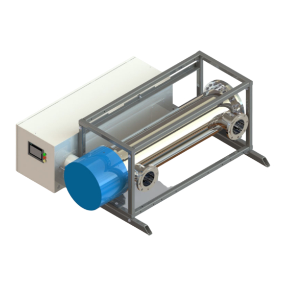
General Information 3.4 System Overview The system is a pressurized UV Chamber that uses high-output low pressure UV Lamps. Figure 1 shows the components for a TOC UV System. These systems have ANSI flange inlet/outlet connections. Figure 2 shows the components for a Liquid Sugar UV System. These systems have sanitary fitting inlet/outlet connections. -
Page 17: Uv Chamber
General Information Figure 2 UV System with Sanitary Flange Option - 1 UV Chamber Stack, Skidded Control Power Panel (CPP) (Clearance required - Service End Cap (Clearance required - Section 7.4) Section 7.2) Inlet/Outlet Connections UVI Sensor (end plate mounted, not shown) (Section 3.4.4) UV Chamber Support Frame (Optional) -
Page 18: Control Power Panel
General Information 3.4.2 Control Power Panel The CPP contains the Lamp Drivers that power and control the UV Lamps. Modular (Skid Mounted) Standalone Figure 3 Control Power Panel 3.4.3 Sample Ports Two optional ports are available for obtaining fluid samples pre-and post UV Chamber. 3.4.4 UVI Sensor (Optional) The UVI Sensor measures UV Lamp Intensity. -
Page 19: Section 4 Lockout Tag Out
Section 4 Lockout Tag Out D A N G E R Obey all warning and caution statements. Refer to Section Read and understand the Operation and Maintenance Manual before operating this equipment. Read all user documentation before performing operations, inspections, repair, or maintenance on this equipment. -
Page 20: Lockout Tag Out Energy Sources
Lockout Tag Out 4.1.3 Lockout Tag Out Energy Sources 1. Use a multi-lock scissor adaptor to lockout each energy source. 2. Attach a completed lockout tag. Include the required information: • Person and company applying the lockout • Reason for the lockout •... -
Page 21: Section 5 System Startup And Shutdown
Section 5 System Startup and Shutdown D A N G E R Obey all warning and caution statements. Refer to Section Read and understand this manual before operating this equipment. Read all user documentation before performing operations, inspections, repair, or maintenance on this equipment. Only competent personnel should undertake operation, repairs, maintenance, or servicing of equipment described in this section of the manual. -
Page 22: Shutdown Procedure
System Startup and Shutdown 5. For Remote - SCADA ON/OFF control: • At the CPP HMI → Verify mode on 'Settings 1’ screen is set to 'Remote - SCADA'. The system then requires only a single signal to start/stop the system. Turn on the signal to start the system from a remote plant controller. -
Page 23: Section 6 Shipment And Storage
Section 6 Shipment and Storage 6.1 Shipping Contents The system consists of two major components, the UV Chamber and the Control Power Panel. Some components may be disconnected at the UV Chamber for shipment. 6.2 How the equipment is shipped The system is delivered to the site by truck. - Page 24 Shipment and Storage Original Instructions...
-
Page 25: Section 7 Installation
Wrench Philips Screwdriver Anti Seize All Aquafine products are carefully inspected and tested before shipment from our plant. Upon delivery, check the packaging and equipment for damage that occurred during shipment. 7.2 Pre-Installation 1. When preparing the site for installation, allow for valves, drain and bypass as part of your plumbing circuit. -
Page 26: Uv Chamber
Installation 6. If your piping system is subject to impulse pressure resulting in “water hammer” condition, a surge tank or other means must be provided to remove this condition; otherwise the extreme momentary pressure may rupture and fracture the Lamp Sleeves. 7. - Page 27 Installation Note: Loosely install the mounting hardware. 5. Level the UV Chamber from side to side and front to back (horizontal). 6. Tighten the mounting hardware. 7. Remove the lifting straps. Original Instructions...
-
Page 28: Install Uv Chamber With Low Profile Skid Base
Installation 8. Install UVI Sensor, if previously removed. Refer to Section 9.7.1 - applies to TOC systems only. 9. Connect UV Chamber Inlet and Outlet to Plant process piping: • For UV Chamber with ANSI Flanges, refer to Section 7.3.5. •... - Page 29 Installation Note: Move UV Chamber Skid to the final installation location. Original Instructions...
- Page 30 Installation Ø 0.78” [ 20mm ] Note: Temporarily move the UV Chamber Skid away from the work area. 10. If a UV Chamber is required to be stacked onto the base assembly, go to Section 7.3.4 and if not, proceed to Step 11. Original Instructions...
-
Page 31: Install Uv Chamber With High Profile Skid Base
Installation 12. Connect UV Chamber Inlet and Outlet to Plant process piping: • For UV Chamber with ANSI Flanges, refer to Section 7.3.5. • For UV Chamber with Sanitary Flanges, refer to Section 7.3.6. 7.3.3 Install UV Chamber with High Profile Skid Base Prerequisites: •... - Page 32 Installation Note: Move the skid to the final installation location. Original Instructions...
- Page 33 Installation Ø 1/2” [ 13mm ] Note: Temporarily move the skid away from the work area. Original Instructions...
- Page 34 Installation Note: Ensure that the fork tines are fully seated in the slots on the Note: Move UV Chamber Skid to the final installation location. skid assembly. Note: Torque the bolts to 58 N.m (43 lbf.ft). Original Instructions...
- Page 35 Installation Note: Torque the bolts to 58 N.m (43 lbf.ft). 14. If a UV Chamber is required to be stacked onto the base assembly, go to Section 7.3.4 and if not, proceed to Step 15. Original Instructions...
-
Page 36: Install A Stacked Uv Chamber
Installation 16. Connect UV Chamber Inlet and Outlet to Plant process piping: • For UV Chamber with ANSI Flanges, refer to Section 7.3.5. • For UV Chamber with Sanitary Flanges, refer to Section 7.3.6. 7.3.4 Install a Stacked UV Chamber Prerequisites: •... - Page 37 Installation Note: Torque the bolts to 58 N.m (43 lbf.ft). 5. If additional UV Chambers are required to be stacked, repeat steps 1, 2, 3 and 4 in this procedure. If there are no additional stacked UV Chambers to be stacked, proceed to Step 6. Original Instructions...
-
Page 38: Connect Inlet And Outlet Process Piping To The Uv Chamber (Ansi Flanges)
Installation 7. Connect UV Chamber Inlet and Outlet to Plant process piping: • For UV Chamber with ANSI Flanges, refer to Section 7.3.5. • For UV Chamber with Sanitary Flanges, refer to Section 7.3.6. 7.3.5 Connect Inlet and Outlet Process Piping to the UV Chamber (ANSI Flanges) Prerequisites: •... -
Page 39: Control Power Panel
Installation 2. Repeat step for the outlet piping. 3. Level the UV Chamber from front to back. Note: The UV Chamber must be installed such that it remains full of process fluid at all times during operation and must be mounted level to ensure it drains properly when service is required. 4. -
Page 40: Electrical Connections
Installation 7.4.1 Electrical Connections Prerequisites: • Apply lockout tag out devices as necessary. Refer to Section • Install the UV Chamber(s) - with or without skid. Refer to Section 7.3. • Install the CPP (for standalone CPP only). Refer to Section 7.4. - Page 41 Installation 7.4.1.1 Local CPP Note: All openings created on the cabinets MUST be filled with equipment marked with the same type rating as the enclosure. Figure 4 Control Power Panel, Bottom view Cutout for Customer Signal Conduit Front of Control Power Panel (HMI side) Note: All openings created on the cabinets MUST be filled with equipment marked with the same type rating as the enclosure.
- Page 42 Installation 7.4.1.2 Remote CPP 7.4.1.2.1 Connect Power from bottom of CPP 1. Remove port plug, and install a strain relief into conduit cutout locations. Figure 5 Control Power Panel Figure 6 Control Power Panel, Bottom view Cutout for Lamp Cable Conduit Cutout for Instrumentation Wire Conduit Cutout for Customer Signal Conduit Front of Control Power Panel (door)
- Page 43 4. Instrument wiring should reference appropriate wiring diagram. Instrument wiring is based upon customer requirements and installed options. Should your requirements differ, contact your local Aquafine representative or Aquafine Customer Service. 7.4.1.2.2 Connect Power from the top of CPP 1. Drill a hole in the top of the Control Power Panel and install a strain relief.
-
Page 44: Assemble The Uvi Sensor
Installation 7.5 Assemble the UVI Sensor Note: Applies to Liquid Sugar applications only. Prerequisites: • Remove the UVI Sensor from the plastic bag. Note: Wear clean cotton or rubber gloves to handle the UVI Sensor. DO NOT contaminate the UVI Sensor window. Materials: Procedure: Original Instructions... -
Page 45: Hydrostatic Test
Installation 4. Set the UVI Sensor aside. 7.6 Hydrostatic Test Prerequisites: • Complete Electrical Connections. Refer to Section 7.4.1. • Remove UV Lamps (if installed). Refer to Section 9.6.2. • Remove UVI Sensor. Refer to Section 9.7.2 - applies to Liquid Sugar systems only. •... - Page 46 Installation Procedure: 1. Fill the UV Chamber with process fluid. a. Stand off to the side and make sure the area is clear of all plant personnel. b. Pressurize the UV Chamber. Refer to Section 9.4. c. Check for leaks. d.
-
Page 47: Section 8 Operation
Section 8 Operation D A N G E R Obey all warning and caution statements. Refer to Section Read and understand this manual before operating this equipment. Read all user documentation before performing operations, inspections, repair, or maintenance on this equipment. Only competent personnel should undertake operation, repairs, maintenance, or servicing of equipment described in this section of the manual. -
Page 48: Alarm And Warning Color Codes
Operation 8.1.2 Alarm and Warning Color Codes The Alarm and Warning indicators are found in the navigation bar. When there is a new alarm or warning, the icon will flash until the user navigates to the Alarm Screen to view the current alarm or warning. Icon Icon Color Definition... -
Page 49: Login Screen
Operation 8.1.4 Login Screen Note: Make sure to log out before leaving the HMI. Push “Logout”. Figure 9 Login Screen To Login: 1. Press the Login Button in the top right hand corner on any of the main screens. 2. Enter the password. 3. -
Page 50: System Overview Screen
Operation 8.2 System Overview Screen Figure 10 System Overview Local Mode, Figure 11 System Overview Remote - Input Mode, TOC Application TOC Application Figure 12 System Overview Local Mode, Figure 13 System Overview Remote - Input Mode, Non-TOC Application Non-TOC Application Figure 14 System Overview Remote - Input Mode, Non-TOC Application with Theoretical Dose Option Item... -
Page 51: System Status Information
Operation Item Description Refer to: Displays Remote Command status. Remote System Section 8.2.4 Note: Only visible when System Setting “Mode” is set to Control Message "Remote - Input" or "Remote - SCADA". Select to manually turn on/off the UV System. Local System Section 8.2.3 Control Buttons... - Page 52 Operation Control Mode Option Description All UV Lamps in UV System will power on and operate at the entered system power level. Manual Note: "The Low UVI alarm is disabled when lamp power level is lower than 100%" message is only visible when the system is configured with a UVI Sensor. Enabled: Available with 100% or Manual Control Mode enabled.
-
Page 53: Local System Control Buttons
Operation 8.2.3 Local System Control Buttons The Local System Control Buttons will only be visible when the System Setting “Mode” is set to "Local". Item Button Description Manually turn on or off the UV System. The displayed button Local System Control On/Off text indicates the current state of the control command (on or off) -
Page 54: Lamp And Driver Information Screen
Operation Item Button/Icon Color Description/Action Refer: Lamp Hours Lamp Hours Select to access the Lamp Hours Screen. Section 8.3.4 Screen The Lamp Hours Approaching End of Life Lamp Hours notification will be visible when a UV Lamp Approaching runtime has reached 8,200 runtime hours End of Life and will remain in place until the UV Lamp Notification... -
Page 55: Lamp And Lamp Driver Information
Operation Item Definition/Action Refer: Reset Hours Button Select to reset lamp hours for the selected UV Lamp. Section 8.3.4 Select to reset a fault for the selected Lamp Driver. Driver Fault Reset Section 8.3.3 Note: The button is visible only when there is an active driver Button fault. - Page 56 Operation Reset lamp hours from the Lamp Hours Screen: Figure 6 Lamp Hours Screen Reset Hours for Individual Lamp 1. Lamp Status Screen → Select the 'Lamp Hours' Button. 2. Lamp Hours Screen → Select the white enterable field beside the UV Lamp number to be reset to zero (0).
-
Page 57: Settings Screen
Operation 8.4 Settings Screen Figure 7 Settings Screen Parameters Unit/Range Description The UV System is set to be remotely controlled and operated Remote - Input using a discrete input. The UV System is set to be remotely controlled and operated using the SCADA signal. -
Page 58: Set 100% Relative Uvi
Operation 8.4.1 Set 100% Relative UVI Note: This process is to be performed after replacing the UV Lamp(s) in the UV Chamber. Figure 8 Set 100% Relative UVI Figure 9 UVI Sensor Calibration Requirements Parameter Option / Range Description System Power 0% - 100% Displays the current UV System Power Level UV Intensity... -
Page 59: Toc Signal Settings
Operation 8.4.2 TOC Signal Settings Figure 10 TOC Signal Settings Parameters Unit/Range Description A TOC Analyzer / Signal is available and connected to the UV System controller. TOC Analyzer / Signal Available A TOC Analyzer / Signal is not available or connected to the UV System controller. -
Page 60: Alarm History Screen
Figure 13 Information Screen Item Text Description Date / Time Displays current set date and time Displays Aquafine Sales Order Number. This number helps Sales Order ###### Aquafine Technical Support reference information about the provided system. ###:###:###:###:### Displays the PLC Software Version... -
Page 61: Date And Time Screen
Operation Item Text Description ###:###:###:###:### Displays the HMI Software Version PLC is in RUN mode. PLC Status Stop PLC is in STOP mode. The program is not being executed. Button Description Refer: Select to exit UV System user interface to view and adjust Control Panel settings. - Page 62 Operation Original Instructions...
-
Page 63: Section 9 Maintenance
Philips Screwdriver Wrench - Adjustable Wrench - Torque Mild Acidic Solution (for example, ® Clean Water ActiClean Gel) or approved by Aquafine Service, food grade cleaner ® Isopropyl Alcohol Lint Free Cloth (Kimwipes Cotton Swab Sleeve Bolt Removal Tool Sleeve Removal Tool... -
Page 64: Maintenance Schedule
Refer to Figure 1 Figure 2 components that are accessible for maintenance. Remember, always using genuine Aquafine parts keeps your warranty and regulatory certifications valid (cULus, CE, UKCA and KC). Table 3 Preventive Maintenance Schedule System... -
Page 65: Depressurize And Drain A Uv Chamber
Maintenance Table 3 Preventive Maintenance Schedule (continued) System Maintenance requirement component Remove the UVI Sensor Sleeve (Section 9.8.1) • Check the Sleeve O-Ring and Sleeve Bolt Washer for UV decay and brittle parts. Replace O-Ring and washer as needed. • Remove any condensation inside the Sensor Sleeve UVI Sensor •... -
Page 66: Pressurize The Uv Chamber
Maintenance Procedure: 1. Stand off to the side of the end plate, open the vent valve and then the drain valve, as the process fluid level drops, the UV System will depressurize. 2. To depressurize only, open the vent valve. 3. -
Page 67: Remove And Install The Service End Cap
Maintenance 9.5 Remove and Install the Service End Cap Prerequisites: • Shut down the UV System. Refer to Section 5 as needed. • Apply lockout tag out devices as necessary. Refer to Section • Depressurize the UV Chamber. Refer to Section 9.3. -
Page 68: Uv Lamp
Maintenance 9.6 UV Lamp UV lamps contain mercury (Section UV Lamps are made of quartz tubing and are breakable. Do not strike, bend or apply pressure or it will break. Discard UV Lamps appropriately. Follow all local regulations. 9.6.1 Storage Requirements for Used UV Lamps Put used UV lamps into the replacement UV lamp shipping container, or a similar container. - Page 69 Maintenance Procedure: Remove: 3. Inspect the UV Lamp pins for: • Evidence of overheating • Moisture • Displaced or bent pins (pins are angled at 10 degrees) 4. Inspect the UV Lamp for: • Cracks or breaks, loose ceramic ends. 5.
- Page 70 Maintenance Install: Note: Always support the UV Lamp with lint free cotton gloved Note: Hand tighten the cap compression nut. hands. Note: The arrow must be positioned at the top of the Lamp Port. Original Instructions...
-
Page 71: Uvi Sensor
Maintenance Post-requisites: • Reset the Lamp Hours when installing a new UV Lamp (Section 8.3.4). 9.7 UVI Sensor Depending on system application, the UVI Sensor design and installation procedure varies. Follow the appropriate procedure in this section. • For TOC applications, the UVI Sensor is UV Chamber body mounted. Refer to Section 9.7.1 removal and replacement procedure. - Page 72 Maintenance Remove: Note: Loosen the nut securing the UVI Sensor. Note: Inspect O-rings for signs of UV decay or brittle parts. Replace if necessary. Install: Note: Orientate the UVI Sensor to position the cable at the bottom as shown. Original Instructions...
-
Page 73: Remove And Replace A Uvi Sensor - Liquid Sugar
Maintenance Note: Tighten the nut to 40 N.m (29.5 lbf.ft) to secure the UVI Sensor. 9.7.2 Remove and Replace a UVI Sensor - Liquid Sugar Note: Applies to Liquid Sugar applications only. Prerequisites: • Shut down the UV System. Refer to Section 5 as needed. - Page 74 Maintenance Procedure: Remove: Note: Inspect O-rings for signs of UV decay or brittle parts. Replace if necessary. Original Instructions...
- Page 75 Maintenance Install: Note: Hand tighten the cap compression nut to secure the UVI Sensor. Original Instructions...
- Page 76 Maintenance 9.7.2.1 Remove and Replace UVI Sensor O-Rings Note: Applies to Liquid Sugar applications only. Prerequisites: • Remove the UVI Sensor. Refer to Section 9.7.2. Materials: • New UVI Sensor O-Rings Procedure: Remove O-Rings: Original Instructions...
-
Page 77: Lamp And Uvi Sensor Sleeve
Maintenance Install O-Rings: 9.8 Lamp and UVI Sensor Sleeve Lamp and UVI Sensor Sleeves are made of quartz tubing and are breakable. Do not strike, bend or apply pressure or it will break. Discard Lamp and UVI Sensor Sleeves appropriately. Follow all local regulations. 9.8.1 Remove and Replace a Sleeve Inspect the Sleeves and Sleeve O-Rings as a part of scheduled maintenance or when a UVI Low alarm occurs. - Page 78 Maintenance • For Lamp Sleeves - Remove the UV Lamp. Refer to Section 9.6.2. • For UVI Sensor Sleeve - Remove the UVI Sensor. Refer to Section 9.7.2 - applies to Liquid Sugar applications only. Tools: 100 lbf.in Materials: • Lamp Sleeve (if required) •...
- Page 79 Maintenance Original Instructions...
- Page 80 Maintenance Install: 1.5” 38mm Notes: 1) Verify that compression spring is in the Lamp Sleeve. Note: Ensure the O-Ring is installed at 1.5” (38 mm) from the open 2) If installing UVI Sensor Sleeve, skip step B. end of the Sleeve. Note: Torque the Sleeve Bolt to 11.3 N.m (100 lbf.in).
-
Page 81: Clean A Sleeve
Build-up on the Sleeves decreases the amount of UV light, and can result in higher UV Lamp temperatures and decreased UV Lamp efficiency. Only use Aquafine Corporation approved cleaning solutions on the Sleeves. Use of unapproved chemicals may result in damage to the equipment. For a list of approved cleaning solutions refer to... -
Page 82: Uv Chamber End Plate
Maintenance 9.9 UV Chamber End Plate 9.9.1 Remove and Install the UV Chamber End Plate Prerequisites: • Shut down the UV System. Refer to Section • Apply lockout tag out devices as necessary. Refer to Section • Depressurize and drain the UV Chamber. Refer to Section 9.3. - Page 83 Maintenance Remove: 1* 1* 2* 2* Note: Slide the Junction Box away from the UV Chamber End Plate. Original Instructions...
- Page 84 Maintenance Note: Inspect the End Plate O-Ring for signs of damage, cracks or wear. Replace if required. Refer to Section 9.9.2. Install: Notes: 1) Make sure the End Plate O-Ring is properly seated in the Note: Torque the bolts in a star pattern to 58.3 N.m (43 lbf.ft). groove before installing the UV Chamber End Plate.
- Page 85 Maintenance 3* 3* 4* 4* Note: Slide the Junction Box towards the UV Chamber End Plate. 5. When service is complete, assemble the prerequisites in the reverse order of the disassembly. Original Instructions...
-
Page 86: Remove And Replace End Plate O-Ring
Maintenance 9.9.2 Remove and Replace End Plate O-Ring Prerequisites: • Remove the UV Chamber End Plate. Refer to Section 9.9.1. Tools: Materials: • New End Plate O-Ring Procedure: Remove: Install: Note: Make sure the End Plate O-Ring is properly seated in the groove. -
Page 87: Baffle Assembly
Maintenance 9.10 Baffle Assembly 9.10.1 Remove and Replace a Baffle Assembly Prerequisites: • Remove the UV Chamber End Plate. Refer to Section 9.9.1. Materials: Procedure: Remove: Install: Note: Remove the Baffle Assembly slowly and evenly. Note: Align the Baffle Plate Guide Rods with the locator sockets on the rear UV Chamber End Plate. -
Page 88: Remove And Replace A Sleeve Bushing
Maintenance 9.10.2 Remove and Replace a Sleeve Bushing Prerequisites: • Remove Baffle Assembly. Refer to Section 9.10.1. Tools: Materials: • New Sleeve Bushing Procedure: Remove: Install: Original Instructions... -
Page 89: Remove And Replace A Baffle Plate Guide O-Ring
Maintenance 9.10.3 Remove and Replace a Baffle Plate Guide O-Ring Prerequisites: • Remove Baffle Assembly. Refer to Section 9.10.1. Tools: Materials: • New Baffle Plate Guide O-Ring Procedure: Remove O-Ring: Install O-Ring: Original Instructions... -
Page 90: Control Power Panel
Maintenance 9.11 Control Power Panel 9.11.1 Remove and Replace a Lamp Driver Replace a Lamp Driver when a Lamp Driver failure alarm occurs. Prerequisites: • Shut down the UV System. Refer to Section • Apply lockout tag out devices as necessary. Refer to Section •... - Page 91 Maintenance Remove: 4* 4* Note: Disconnect the Ethernet cables from the Lamp Driver. Original Instructions...
- Page 92 Maintenance Note: Disconnect the Ethernet cable and terminating resistor from the Lamp Driver. Install: Note: Connect the Ethernet cable and terminating resistor to the Note: Install wires in order. 1=Neutral, 2 = Ground, 3 = Line. Lamp Driver. Original Instructions...
- Page 93 Maintenance 2* 2* Note: Make sure the notched tab on the backside of the Lamp Driver Note: Connect the Ethernet cables to the Lamp Driver. is fully seated under the mounting bar tab. Original Instructions...
-
Page 94: Air Filters
Maintenance Note: Install wires in order. 1 = Grey Wire, 2 = White Wire, 3 = Yellow Wire, 4 = Brown Wire 7. Change the Rotary Switch addresses on the new Lamp Driver to match the addresses on the removed Lamp Driver. -
Page 95: Section 10 Troubleshooting
Injury or damage to the equipment due to improper testing, handling or maintenance will not be covered under the manufacturer’s warranty and is the responsibility of the individual performing the troubleshooting. If there is ® any question about a procedure, contact Aquafine Corporation before service. 10.1 Alarms... -
Page 96: Alarm Conditions
Troubleshooting Alarm Description ELCB - Alarm Indicates whether or not there is an ELCB alarm Indicates that the temperature switch in the enclosure is experiencing temperatures above the Enclosure Temperature - allowable limit. The enclosure power will shutdown after 15 minutes if the high temperature Alarm condition persists. - Page 97 A software change is required to change the Sleeve type installed. UV Lamp and Lamp Sleeve type. Contact your local Distributor or Aquafine support. The socket should be inspected to ensure that the UV Lamp Improper Connection connection is tight and no damage is present.
-
Page 98: Non Alarm Conditions
Troubleshooting Condition Possible Cause Possible Solution One or more UV Lamps have Replace all EOL UV Lamps (Section 9.6.2). Reset the Lamp Lamp Hours EOL reached the end of their useful Hours (Section 8.3.4). life Verify that the cables joining all the Lamp Drivers are good and Wiring connection broken the wiring connection from the first Lamp Driver to the last is not broken. -
Page 99: Uv Lamp
Troubleshooting 10.3.2 UV Lamp Condition Possible Cause Possible Solution Systems in which the UV is turned ON/OFF frequently (more Lamp Cycling than 3 times) will cause the UV Lamp filament damage. The electrical power should be within 5% of the name plate Low Electrical Power voltage. -
Page 100: Uvi Sensor
Troubleshooting 10.3.4 UVI Sensor Condition Possible Cause Possible Solution Inspect the UV Lamp. Replace the UV Lamp, if required. Failed UV Lamp(s) (Section 9.6.2) Replace the UV Lamp (Section 9.6.2) UV Lamps have reached End Note: Continued use of the UV Lamps that have exceeded EOL of Life means the system will no longer be able to perform as expected. -
Page 101: Section 11 Replacement Parts And Accessories
• Part number and description of the replacement part or accessory ® If a replacement part is not listed, contact Aquafine Corporation There are two (2) elastomer types available for use in the UV system. Refer to Table 5 for wetted elastomers types and their intended use. -
Page 102: Uvi Sensor
Always use the same type of UV Lamp and Lamp Sleeve (i.e. Standard or High Performance) as was used when the system was purchased. A software change is required to change the UV Lamp and Lamp Sleeve type. Contact your local Distributor or Aquafine support. 11.2 UVI Sensor Note: Applies to TOC applications only. -
Page 103: Systems Without Uvi Sensor
Replacement Parts and Accessories 11.3 Systems without UVI Sensor Note: Applies to TOC applications only. Figure 18 UVI Sensor - Plug Kit Item Description Part Number O-ring, .426ID x 0.05, FKM, FDA 002222 O-ring, 1/2 x 1/16, FKM, FDA 002190-014F Sensor Port Plug Kit 52863-V Original Instructions... -
Page 104: Uvi Sensor
Replacement Parts and Accessories 11.4 UVI Sensor Note: Applies to Liquid Sugar applications only. Figure 19 UVI Sensor Item Description Part Number Sleeve Cup Nut 17489-8 Sleeve Bolt 52838 Sleeve Bolt Washer 53439 O-ring, 1 x 1/8, EPDM, EU1935, FDA 002304-214 Sensor Assembly 798325... -
Page 105: Baffle Assembly
Replacement Parts and Accessories 11.5 Baffle Assembly Figure 20 Baffle Assembly Item Description Part Number Sleeve Bushing 798205 O-Ring, .605 X .102, FKM, FDA 52796-114 O-Ring, 5/8 x 3/32, EPDM, EU1935, FDA 002304-114 Refer to Table 5 for wetted elastomer types and their intended use. Always refer to site-specific requirements to determine wetted elastomer type required for the provided system. -
Page 106: Uv Chamber
Replacement Parts and Accessories 11.6 UV Chamber Figure 21 UV Chamber Components System Model AVT20 / AVT36 / AVT44 / AVT48 / Item Description AVT20-HP AVT36-HP AVT44-HP AVT48-HP Part Number Limit Switch 917626-RLVASSY Temperature Switch, 52855 40C operational temperature Temperature Switch, 52855-065 55C operational temperature (Liquid Sugar Applications only) -
Page 107: Port Plugs - Flanged Connections - Toc Applications
Replacement Parts and Accessories 11.6.1 Port Plugs - Flanged Connections - TOC Applications Figure 22 Port Plugs - Flanged Connections Item Description Part Number Valve, Bleed 1/4" MNPT 316 907797-4NBS316 Cap, Female 3/4" 316 NPT 53107-1216 Sample Port Plug 907782-0422316 Original Instructions... -
Page 108: Port Plugs - Sanitary Ferrule Connections - Liquid Sugar Applications
Replacement Parts and Accessories 11.6.2 Port Plugs - Sanitary Ferrule Connections - Liquid Sugar Applications Figure 23 Port Plugs - Sanitary Ferrule Connections Item Description Part Number End Cap, 1/2 & 3/4" Ferrule 793643-001 Gasket, Sanitary 3/4" 798291-007 Clamp, Sanitary 1/2” & 3/4” 798314 Valve, 1/2"... -
Page 109: Control Power Panel
Replacement Parts and Accessories 11.7 Control Power Panel Refer to Electrical Drawings, Bill of Materials for additional CPP replacement parts. Item Description Part Number Lamp Driver 53126 Temperature Sensor Kit (includes Thermostat) 52827 Thermostat 53201 Cooling Fan, 230VAC 323/353CFM 916850-3243100 Cooling Fan Filter, 13"... - Page 110 Replacement Parts and Accessories Original Instructions...
Need help?
Do you have a question about the Avant Series and is the answer not in the manual?
Questions and answers