Table of Contents
Advertisement
READ THIS MANUAL
This manual covers the installation, operation and general maintenance
requirements for Aquafine Ultraviolet Water Treatment Equipment.
O
p
t
i
m
O
p
t
i
m
O
p
t
i
m
O
p
t
i
m
It is imperative that those responsible for the installation of this
SAFETY
equipment, as well as operating personnel, read this manual and
ISSUE
carefully follow all instructions and guidelines
OPERATORS AND INSTALLERS MUST COMPLY WITH
OPERATIONAL SAFETY REQUIREMENTS.
1.800.423.3015
email:
PLEASE KEEP FOR PERMANENT REFERENCE
Part No. 120, Rev. 6.0 10/04
Disinfection
Optima HX
a
H
X
&
a
H
X
&
a
H
X
-
U
S
e
r
i
e
s
a
H
X
-
U
S
e
r
i
e
s
(outside California and within domestic USA)
sales@aquafineuv.com
I
n
s
t
a
l
l
a
t
i
o
I
n
s
t
a
l
l
a
t
i
o
O
p
e
r
a
t
i
o
n
O
p
e
r
a
t
i
o
n
. EQUIPMENT
web:
www.aquafineuv.com
n
a
n
d
n
a
n
d
M
a
n
u
a
l
M
a
n
u
a
l
1
Advertisement
Table of Contents

Related Manuals for Aquafine optima hx series


Summary of Contents for Aquafine optima hx series
- Page 1 READ THIS MANUAL PLEASE KEEP FOR PERMANENT REFERENCE Part No. 120, Rev. 6.0 10/04 This manual covers the installation, operation and general maintenance requirements for Aquafine Ultraviolet Water Treatment Equipment. Disinfection Optima HX & & It is imperative that those responsible for the installation of this...
-
Page 2: Table Of Contents
PURPOSE AND SCOPE ....................3 SYSTEM DESCRIPTION....................4-12 Unit Description....................5-6 Standard Monitoring System ................7-9 Aqualogic 2000™ Monitoring System ............10-12 INSTALLATION......................13-18 Guidelines ...................... 13-14 HX and HX-U Unit Do's and Don'ts .............. 14-15 Quartz Sleeve Installation.................. 16 UV Lamp Installation.................. -
Page 3: Purpose And Scope
Purpose and Scope Purpose: To provide instructions for the installation and operation of the Optima HX and Optima HX-U series. Scope: This instruction is intended for personnel that have a working knowledge of servicing electrical and mechanical equipment. Warning: • Remove all electrical power to the unit before servicing the unit. -
Page 4: System Description
The Optima HX product line is designed to offer the latest in low pressure UV technology over a wide range of application flow rates. It includes the critical quality and performance ® features that have made Aquafine the standard in UV water treatment for over 50 years, while doing so in a highly cost-effective manner. -
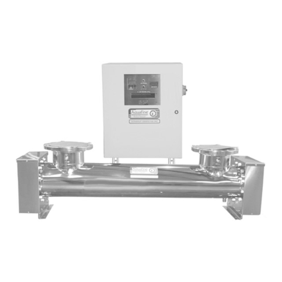
Page 5: Unit Description
Unit Description: Fig. A HX S ERIES DENTIFIED LEMENTS Elements to identify the HX Series Unit are: See Fig. A above. 1. Treatment Chamber 2. Sample Port - optional 3. Gasket Endplate 4. Control Cabinet 5. Quartz Sleeves and Lamps – located inside the treatment chamber 6. - Page 6 Socket Covers The socket covers on either end of the treatment chamber protect the lamp socket assemblies. Quartz Sleeves And Lamps The quartz sleeves and lamps fit inside the UV treatment chamber. The lamp sockets connect to the lamps, creating a water resistant seal and a vibration-proof grip.
-
Page 7: Standard Monitoring System
STANDARD MONITORING SYSTEMS Fig. A TANDARD ONITORING YSTEM ONTROL ANEL ON AN PTIMA Elements to identify the HX Standard Monitoring System are: UV LED Operational Display Main Power Switch Running Time Meter Integrated Monitoring System Lamps Operational - optional Lamp Out Alert - optional Fig. - Page 8 Integrated Monitoring Station: ® The Aquafine UV Integrated Monitoring System consists of 3 basic components: the Monitoring Station, the Detector and the Cable with connector. The corresponding labels identify the different controls. The use of each of these controls is described in the Monitoring Station Operation section.
- Page 9 The Detector is provided with an O-ring. This O-ring is necessary certificate. ® to create the proper seal when the unit is installed in the Aquafine treatment chamber. Be sure that the O-ring is present when installing the Detector in the UV treatment chamber.
-
Page 10: Aqualogic 2000™ Monitoring System
AQUALOGIC 2000™ MONITORING SYSTEM The Aqualogic 2000™ is a microprocessor-based system. The Aqualogic 2000™ system consists of two printed circuits boards; the Current Sensing Board (CSB) and the Status Display Board (SDB). The system monitors Lamp Status, UV Intensity, Low UV Alarm Point, Lamp Out Alert, Temperature Alarm, unit running time and unit “ON/OFF”... - Page 11 AQUALOGIC 2000™ MONITORING STATION : The corresponding labels identify the different controls. The use of each of these controls is described in the Monitoring Station Operation section. See page 23. . B A 2000™ S – QUALOGIC TATUS ISPLAY OARD RONT The backside of the Monitoring Station is not accessible to the user after the unit is installed.
- Page 12 O-ring. This O-ring is necessary to create the proper seal ® when the unit is installed in the Aquafine UV treatment chamber. Be sure that the O-ring is present when installing the Detector in the UV treatment chamber.
-
Page 13: Installation
40°F (4°C) to 80°F (27°C). Should your requirements differ, please ® ® contact your local Aquafine representative or Aquafine Customer Service. B) As an ultraviolet UV treatment unit does not introduce any chemical residue within the water, it is desirable to install the unit as close as possible to the point-of-use in order to avoid potential recontamination by discharge pipes, fittings, etc. -
Page 14: Hx And Hx-U Unit Do's And Don'ts
If the external transformer is factory installed local to the electrical enclosure, the secondary terminations are factory wired by ® Aquafine If the external transformer is required, the transformer primary connections to the customer’s incoming power shall be made in... - Page 15 C) and ° ° ® F (49 C), contact Aquafine Customer Service D) For heat sanitization it is recommended that stainless steel compression nuts be used in place of CPVC compression nuts. The selection of the Elastomer should be considered.
-
Page 16: Quartz Sleeve Installation
UARTZ LEEVE NSTALLATION The quartz sleeves designed for this series are open on both ends. The following are the guidelines and procedure for quartz sleeve installation. 1. Turn off all power to the unit. 2. Wear clean cotton gloves to prevent contamination of the quartz sleeves. 3. -
Page 17: Uv Lamp Installation
(UV) L LTRAVIOLET NSTALLATION Once it has been verified that there are no leaks in the system, the unit is ready for UV lamp installation. 1. Remove all the power to the UV unit. 2. Depressurize the system. 3. Wear clean cotton gloves to prevent contamination of the UV lamps. 4. -
Page 18: Powering Up
POWERING UP: Prior to turning on the UV unit, the following must be verified: 1. The UV chamber should be filled with water. The flow of water for the initial filling should not exceed 50 GPM. Failure to comply may result in quartz sleeves breakage. -
Page 19: Hx And Hx-U Series Operation
& & PERATIONAL UIDELINES 1) Release the pressure in the UV treatment chamber before attempting to remove the protective covers and sealing items. 2) Disconnect all power to the UV unit before servicing. The unit operates on high voltage and should only be serviced by qualified personnel. 3) Do not allow the unit to overheat by operating without water flow. -
Page 20: Integrated Monitoring System
INTEGRATED MONITORING SYSTEM for HX or HX-U series The Monitoring Station has the capability to display continuously the level of irradiance detected by the sensor in irradiance units (µW/cm ) or in percentage value (%). See Fig. A # 8. In addition, the Monitoring Station also reports the current temperature value of the water either in degrees Celsius or Fahrenheit. - Page 21 UV ALARM SET button Displays the user-set alarm level in % value under which the system will trigger the low level UV alarm protocol. The alarm level % is displayed only while this button is pressed. SET ALARM LEVEL potentiometer By turning this control, the user-set alarm level in % value under which the system will trigger the low level UV alarm protocol is modified.
-
Page 22: Setting The Uv
UV PROCEDURE FOR SETTING THE MONITORING STATION Gradually start the normal flow rate. Bring the unit up to normal operating pressure and temperature. Turn on the UV lamps – wait a minimum of 15 minutes. First set the “SET 100% LEVEL”. See below for instructions. -
Page 23: Aqualogic 2000™ Monitoring System
AQUALOGIC 2000™ MONITORING SYSTEM The Aqualogic 2000™ has the capability to display continuously the level of irradiance detected by the sensor in irradiance units (µW/cm ) or in percentage value (%). Reading can be measured and displaced in either Absolute (0-5000µW/cm ) or Relative (0-100%) by the DIPswitch SW7-8. - Page 24 1. Running Time Indicator The running time Indicator will illuminate when the elapsed time of the unit is displayed on the Cycle/Hour display. Aqualogic controls are equipped with a re-settable running time meter and are used to determine the number of hours on the equipment and for maintenance.
-
Page 25: Setting The Set 100% Level
preventing overheating conditions. When the water temperature drops below 100°F, the UV lamps will re-energize. A SPDT contact is available for customer interfacing during a High Temperature Condition. The contact will enable interfacing into a central monitoring system (PLC, DCS, etc). During the high temperature fault condition, the High Temperature LED will illuminate. -
Page 26: Setting The Aqualogic 2000™ Status Display Board
Setting the Aqualogic 2000™ Status Display Board: Adjust the dipswitches, per system requirements. 1) SW-5 Display Primary Time/Cycle There are two elapsed clock memories in the system. One is the elapsed time that can be reset with SW-2 and the total accumulated time. The SW-5 switch allows the user to display the total accumulated operational hours and cycles on the unit. - Page 27 SW-7 DIP Switch The Aqualogic 2000™ DIP switch 7 allows the user to set different parameters related to the operation. See table below. SWITCH POSITION POSITION FUNCTION Open Closed SW7-1 Sets the Low UV Alarm Set Point (DEFAULT) TT/CC reset Allows user to reset the indicated elapsed Deactivated SW7-2...
-
Page 28: Preventative Maintenance
The following provides users of Aquafine UV treatment equipment with recommendations and procedures that will maximize the efficiency, consistency, reliability, and longevity of the equipment. Once the equipment is properly installed and fully operational, this will provide time-oriented guidelines for:... -
Page 29: Unit Maintenance
CAUTION! The most important consideration for proper installation, operation and maintenance of any piece of equipment is operator safety. The following caution statements directly relate to operator safety. Please review with all applicable personnel to ensure continuous compliance. The following safety requirements are mandatory. Failure to carefully follow them can cause injury to the operator and damage to the UV unit. -
Page 30: Quartz Sleeve Maintenance
If dirty, use the following procedures. Should this be insufficient, they should be replaced. To place an order, ® please contact your local Aquafine representative or call customer service. 1. Turn off the water to the unit. 2. Disconnect the electrical circuit. -
Page 31: Checking For Leaks
Checking for Leaks: To ensure there are no leaks, a visual inspection of the treatment chamber should be made. The source of any leaking should be found and repaired. Follow the installation procedures of the quartz sleeves and UV lamps for replacing the O-ring. See pages 16 thru 17. -
Page 32: Lamp Operation Lamp-Out Alert
BURG-S “L” Type GOLD-L BURG-L COLORGUARD™ UV LAMP CERAMIC BASES ARE EXCLUSIVE TO AQUAFINE AND MAKE MIXING OF DIFFERENT LAMP TYPES VIRTUALLY IMPOSSIBLE DURING LAMP CHANGE OUT. NOTE: The Lamp Out Alert alarm and function will not activate for the first 30 seconds of operation after the lamps have been turned “ON”. -
Page 33: Inspecting The Lamp Socket
Inspecting the Lamp Socket: When replacing lamps, inspect the lamp socket contacts and related hardware. They should be inspected for corrosion of the metal contact, deterioration of the material or burning. 1) Be sure all power to the equipment is disconnected. 2) Inspect the condition of the socket retainer caps. -
Page 34: Cleaning The Detector Window
Cleaning the Detector Window: 1) Shut off the flow and release the pressure. 2) Shut off all power to the UV unit. 3) Remove the cable by twisting the connector terminal counterclockwise. The connector will slide off. 4) Unscrew the Detector. 5) Use a lint-free cloth with alcohol and very carefully wipe the lens face on the front of the Detector. -
Page 35: Troubleshooting Guidelines
STANDARD SYMPTOM PROBABLE CAUSE REMEDY UV SYSTEM NON- UV Lamp Maintenance Lamps may require maintenance. PERFORMANCE - If the capacity of the equipment exceeds BACTERIA Water Flow Too High the design capacity, then performance will be compromised. If the water has debris, chemicals or Water Quality materials that absorb the UV energy, the performance will be compromised. - Page 36 SYMPTOM PROBABLE CAUSE REMEDY LAMP IS NOT The UV lamp should be inspected for Lamp Failure OPERATING ON LED damage. Replace UV Lamp. DISPLAY, IS NOT YELLOW The socket should be inspected to insure Lamp Connection that the lamp connection is tight and no damage is present.
- Page 37 SYMPTOM PROBABLE CAUSE REMEDY PREMATURE (LESS Systems in which the UV is turned “ON“ THAN 9,000 HOURS) Lamp Cycling and “OFF” frequently (more than 3X) will LAMP FAILURE cause lamp filament damages. Low equipment power will cause damage to the electrical equipment. The electrical Electrical Power power should be within 5% of the nameplate voltage.
-
Page 38: Aqualogic 2000
AQUALOGIC 2000™ SYMPTOM PROBABLE CAUSE REMEDY UV SYSTEM NON- If the capacity of the equipment exceeds PERFORMANCE Water Flow Too High the design capacity, then performance will be compromised. If the water has debris, chemicals or Water Quality materials that absorb the UV energy, the performance will be compromised. - Page 39 SYMPTOM PROBABLE CAUSE REMEDY LAMP OUT ALERT SDB board is set for the Check SW-8 DIP switch settings in wrong number of lamp INDICATOR LAMP IS relation to equipment model number. ILLUMINATED inputs. LAMP OUT DOES NOT INDICATE WHEN ONE OR Time delay in system Wait 30 seconds after power has been program.
- Page 40 SYMPTOM PROBABLE CAUSE REMEDY LAMPS WILL If the High temperature LED is “ON” and NOT TURN ON. Temperature Signal the temperature displayed is not correct or floating or the UV drifting, the UV unit will shut “OFF”. Check Temperature probe is not the controller connection on J9 of the connected.
- Page 41 SYMPTOM PROBABLE CAUSE REMEDY LOW UV INTENSITY If water is present in the quartz sleeve, the IS ILLUMINATED. leak should be repaired immediately. Leaking/Water in Quartz Water can cause the lamp socket to arc, Sleeve corrosion on the lamp pins, burning of the lamp sockets and damage to the ballast and LED components.
- Page 42 SYMPTOM PROBABLE CAUSE REMEDY LEAKING If the unit is operating with compression nuts manufactured with CPVC (gray plastic) and has been exposed to elevated temperatures, material Heat Damaged Part damaged. Excessive heat can distort the plastic material, resulting in a loss in compression of the O-ring seal.
-
Page 43: Warranty Information
4” and 75 lbs, for 6” or above. Torsion loads or side loading of the risers should be eliminated. ® 8. Use of components other than those provided or authorized by Aquafine 9. Failure to correct overhead piping connection leaks or compression nut seal leaks which result in damage to the electrical components. -
Page 45: Replacement Parts List
Part Part No. O-rings – for quartz sleeves EPDM 4253 O-rings – for quartz sleeves Viton 40413 Detector O-ring – Viton 40432 Cylinder O-ring – for Optima “F” series EPDM 15601 Cylinder O-ring – for Optima “F” series Viton 40428 Cylinder O-ring –... - Page 46 Part Part No. UV Lamps SE 254 NM – BURGUNDY for validated disinfections “S” Type BURG-S “L” Type BURG-L Quartz Sleeve “S” Type 25mm 3184 Quartz Sleeve “L” Type 25mm 3198 Lamp Socket – 30” Lead Wires 40569-3 Lamp Socket – 90” Lead Wires 40569-8 Lamp Socket –...
Need help?
Do you have a question about the optima hx series and is the answer not in the manual?
Questions and answers