Table of Contents
Advertisement
Quick Links
Advertisement
Table of Contents

Related Manuals for Genvex OPTIMA 314

Summary of Contents for Genvex OPTIMA 314
- Page 1 OPERATING INSTRUCTIONS OPTIMA 314 THE AIR WE BREATHE...
-
Page 2: Table Of Contents
TABLE OF CONTENTS 1. Installation .....................................4 2. Programming the Optima 314 controller ........................5 3. Display .....................................6 4. Start-up ....................................7 5. Controller menu ...................................8 6. Controller settings ................................9 7. Further explanations of humidity and district heating control ..............23 8. Maintenance ..................................24... - Page 3 1. INSTALLATION OF OPTIMA BASIC Important information Safety information This appliance can be used by children aged from 8 years and above and persons with reduced physical, sensory or mental capabilities or lack of experience and knowledge if they have been given supervision or instruction concerning use of the appliance in a safe way and understand the hazards involved.
-
Page 4: Installation
50 meters. To remove the display , carefully push the plastic clip (locking mechanism) as indicated on the picture. For additional information on connecting the control panel to Optima 314 – please refer to the electrical diagram in the installation manual. -
Page 5: Programming The Optima 314 Controller
3/4” RG Internet 3/4" RG connector on top of the machine or (connectors marked connection 90W Supply air fan 90W Extract air fan with “display”) or directly on the Optima 314 Controller Bypass PCB. Display connection 1200W Electric preheater (Optional) -
Page 6: Display
If EH5 is set to 0 the icon will be removed from the display. At the bottom of the display: *Micro USB interface for PC programming of Optima 314 controller parameters. *micro sd card – card reader for firmware update of controller and... -
Page 7: Start-Up
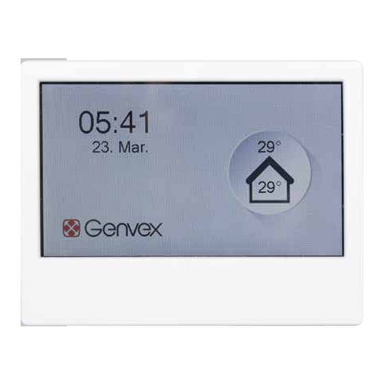
4.1 Userinterface Optima Touch – initial start up 4.2 Userinterface Optima Touch – screen saver During initial start up of the Optima 314 ventilation Depending on the screen saver settings in menu D – display. controller and with the Optima Touch connected to the The current screen displayed will switch back to screen controller, the following information will be shown. -
Page 8: Controller Menu
5. CONTROLLER MENU 5.1 Structure, user and service menu in Optima Touch The user and service menu structure in the Optima Touch display is organized in the following sections A. User: main user settings B. Scheduler: calender schedules for change of fanspeeds and temperature setpoints C. -
Page 9: Controller Settings
6. CONTROLLER SETTINGS Menu Description Factory setting and (max. / min values A1 - Reheating If there is a reheater fitted to the system, you can choose if the A1: Off reheater should operate. If the set point is set to OFF, the heater will (On - Off) not operate, even when this is necessary. - Page 10 To deactive password promt use 0000 as password D5 - Firmware Optima 314 controller and display can be firmware updated by use update of a micro-SD card inserted into the SD card reader of the Optima touch display.
- Page 11 Saves the settings from the Optima314 controller to the display EA2 - Load settings Loads settings stored in EA1 and transfers data to a new Optima 314 EB - Fan speed EB1 - Level 1 Supply air EB1: 40%...
- Page 12 Menu Description Factory setting and (max. / min values) EB - Fan speed EB9 - min air volume mode EB9: On levels If set to on, the supply and extract fans will automatically increase (on/off) fanspeed to the values set in EB10 and EB11 - when the heatpump activates.
- Page 13 Menu Description Factory setting and (max. / min values) EC - Regulator EC5 – H3 relay options. EC5: Preheat Preheat = the relay will activate a preheater connected to the relay H3. (preheat/ reheat / Adjust setpoint EC1 to T3 preheat or T5 preheat. always on) Reheat = the relay will activate a reheater connected to the relay H3.
- Page 14 Menu Description Factory setting and (max. / min values) EC - Regulator 10: It is possible to connect a solar pump controlled according to EC8 to the relay H9. The relay is off when T8 domestic hot water temperature reaches 65 °C 11: The relay is on if there is no error on the fire control system set in menu EJ1 connected to the Combi unit.
- Page 15 Menu Description Factory setting and (max. / min values) EC – Regulator EC8 – Solar Hysteresis EC8 : 5 If a solar collector is connected to the coil of the boiler, use this option (0-5 C) to input the temperature difference between the temperature in the solar collector (T9) and the domestic water temperature (T8) that should be reached before the solar pump starts.
- Page 16 Menu Description Factory setting and (max. / min values) ED - Electrical ED9 - Reheat reg. ED9: 40 sec heating The Reheat Cycle function works, as follows: E.g. necessary output 50% (10-120sec) and cycle = 60 sec means that the controller will switch the reheater on for 30 sec and off for 30 sec.
- Page 17 Menu Description Factory setting and (max. / min values) EF - Filter EF3 - Filter/stop EF3: off (On/Off) To ensure that the filters are changed when the filter change alarm is active, the set point can be set to ON. The system will then stop automatically after 14 days if the filters have not been changed in the meantime.
- Page 18 Menu Description Factory setting and (max. / min values) EH – Heatpump EH4 – Min outdoor cooling EH4: 15 C (0-20 C) settings To prevent the cooling function to activate at low fresh air temperatures and from blowing cold, unheated air into the dwelling, use this function to configure the lowest fresh air temperature at which cooling may be enabled.
- Page 19 Menu Description Factory setting and (max. / min values) EH – Heatpump EH13 – External override EH13: Scheduler settings • Scheduler = the calender programme will determine the operation of (scheduler / solar the Combi unit. panel / smart grid) •...
- Page 20 Menu Description Factory setting and (max. / min values) EI1 - CO2 control EI1: Off On = activates external sensors for demand control (if available) (On/Off) Off = no external sensors for demand control available EI2 - CO2 setpoint EI2: 800 PPM setpoint for desired CO2 level in PPM.
- Page 21 Menu Description Factory setting and (max. / min values) EK - Mixing valve PLEASE NOTE: control If no external outdoor air temperature sensor has been connected the controller, the built in fresh air temperature sensor in the MVHR is used as reference for calculating weathercompensation temperature setpoints.
- Page 22 Menu Description Factory setting and (max. / min values) EK - Space heating EK10 - Heating PI P EK10: 20 control PI controller P-band (0 - 255) By increasing this value the controller will try to reach the setpoint temperature faster (with a risk of overshooting the setpoint) EK11 - Heating PI I (x10) EK11: 50 PI controller I-band...
-
Page 23: Further Explanations Of Humidity And District Heating Control
7. FURTHER EXPLANATIONS OF HUMIDITY AND DISTRICT HEATING CONTROL 7.1 Humidity control explanation Example 1: At a fresh air temperature of 10°C the RH- control aims for 55 % humidity measured Setting range EG1 in the extract air. and EG2 Example 2: At a fresh air temperature of 20°C the RH-control aims for 60 % humidity... -
Page 24: Maintenance
Vacuum cleaning or using pressurised air on the filters is not apply to PTC electrical heaters. not recommended. Recommended filters to be used: Original Genvex filters in The system is not running. Unit stopped quality Coarse / G4 = Standard filter (typically used on Possible error extract air side) ;... - Page 25 Optima 314 Main menu Factory settings Possible settings A – User A1 - Reheating On - Off A2 - Humidity control On - Off A3 - DHW temperature 52°C 0 - 60°C A4 - DHW Element Temp 50°C 0 - 65°C...
- Page 26 Optima 314 Main menu Factory settings Possible settings EC – Regulator EC1 - Frost protection Fan Reduction Off / T3 preheat / T5 preheat / Fan Reduction EC2 - Frostreduktion 8°C -10°C - +10°C EC3 - Release system stop On - Off...
- Page 27 Optima 314 Main menu Factory settings Possible settings EH - Combi Settings EH10 - Balanced defrost On - Off EH11 - Constant on/off On - Off EH12 - Constant @ temp 5°C 0 - 10°C EH13 - External override Scheduler...
- Page 28 Please visit www.genvex.com to see a list of our distributors KVM-Genvex A/S • Sverigesvej 6 • DK-6100 Haderslev • Tel.: +45 73 53 27 00 • salgogsupport@genvex.dk • www.genvex.com...
Need help?
Do you have a question about the OPTIMA 314 and is the answer not in the manual?
Questions and answers