Table of Contents
Advertisement
Quick Links
Advertisement
Table of Contents

Summary of Contents for EGO EasyPro Series
- Page 1 EasyPro Series User manual E a s y P r o - P 1.8 / P2 / P2.5...
-
Page 2: Table Of Contents
CON TENT PRODUCT OVERVIEW ..............................- 5 - 1.1 Product Features ............................... - 5 - 1.2 Product Specification ............................... - 6 - 1.3 Panel size ........ - Page 3 Please read this manual carefully before installing, powering up, operating and maintenance of this product. Follow safety instructions in this manual and on the product. If you have any questions, please seek help from EGO Display. Beware of Electric Shock! •...
- Page 4 • Maintain good ventilation around the display screen, controller, power supply and other devices, and keep a mini mum 0.1 meter gap with other objects. • Do not stick or hang anything on the screen. • Do not modify the product, do not add or remove parts. •...
- Page 5 Warning: Changes or modifications to this unit not expressly approved by the party responsible for compliance could void the user’s authority to operate the equipment. NOTE: This equipment has been tested and found to comply with the limits for a Class A digital device, pursuant to part 15 of the FCC Rules.
-
Page 6: Product Overview
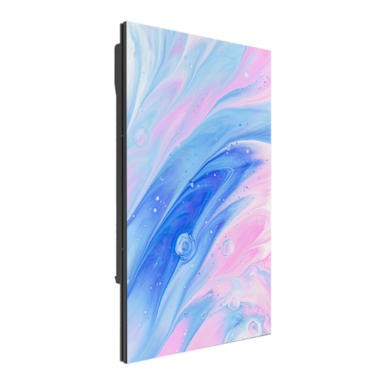
1 PRODUCT OVERVIEW The EasyPro series is an indoor high-definition fixed display specia lly developed for the commercial display market. It features all -in-one minimalist design and convenient installation. The size of the panel is 320x480mm, and the control card and power supply unit are integrated inside. The whole panel is pre-installed an d shipped. -
Page 7: Product Specification
1.2 Product Specification Parameter LED type SMD1515 black SMD1515 black SMD151 5 black Pixel pitch (mm) 1.86 Panel size 320×480×55 320×480×55 320×480×55 physical (W×H×D)/(mm) parameter Panel resolution 172x258 160x240 128 ×192 Panel weight(㎏) Module size (W×H)/(mm) 320×160 320×160 320×160 Brightness(nit) Refresh rate(Hz)... -
Page 8: Panel Size
1 .3 Panel size (side view and rear view , unit: mm) 1 .4 Module size (front view, unit: mm) - 7 -... -
Page 9: Product Componets
2 PRODUCT COMPONETS 2.1 Panel Location for safety rope (optinal) Module Power supply and receiving car d R ear cover 2.2 Accessories Signal cable : T-type power cable : Power cable to LED wall :The length will be configured according to the client's requirements - 8 -... -
Page 10: Preparations Before Installation
3 Preparations before installation 3.1 Tools for installation Picture Tool type Function Knife Open the package Vacuum front panel front service service tool tool Needle nose Adjust the flatness by pliers Maintenance and disassembly PH2 screwdriver Module & power supply &... -
Page 11: On-Site Environment Requirements
3.2 On-site environment requirements 1. Narrow pixel pitch series products need to test the field temperature and humidity before installation, ensure that the temperature is within 35 ℃, humidity within 70%RH can be installed; 2. For the environment temperature higher than (35℃, 70%RH), the screen under high temperature and humidity, will make the LED lamp bead there is a hidden danger of moisture, resulting in a large number of LED lamp bead damag e screen body;... - Page 12 3. Wiring sequence: Connect the Panel with the connecting box power cable first, and then connect the box with the 3 main power cable from the distribution box or socket to the bottom bo x. 4. Power connection: First confirm that the power supply end is in the "off" state, must use the electrical end to start the connection (set a switch or distribution box, etc.).
-
Page 13: Product Installation
4 PRODUCT INSTALLATION 4.1 Main power cable Preparation before connection Before connecting: Before supplying power to the entire screen, check whether the power cables are connected between boxes and whether the main power cables are correctly connected between the screen and the distribution box. -
Page 14: Installation Instructions
Power Product Model Standard box size Power cable consumption Number (mm) with load (220V) with load (110V) (maximum) EasyPro-P1.8 320x480x55 320 W/ ㎡ EasyPro-P2 320x480x55 325 W/ ㎡ EasyPro-P2.5 320x480x55 330 W/ ㎡ 4. 2 Installation instructions Product installation type Installation type Remark Steel structure magnetic... - Page 15 (Installation instruction) (Rear view after installation ) - 14 -...
-
Page 16: Product Maintenance
5. PRODUCT MAINTENANCE 5 .1 Panel maintenance EasyPro series containers can be quickly removed using a vacuum adsorption tool 3- 5 seconds. Attach the front maintenance tool to the surface of the container to be removed, press a switch, and pull out the maintenance tool for 3-5 seconds. -
Page 17: Module/Receiving Card/Psu Maintenance
5.2 Module/receiving card/PSU maintenance Module maintenance Picture Use the maintenance tool to remove the box. Use the Phillips screwdriver of PH2 to remove the four screws from the rear cover of the container . The module can be replaced directly after removing the aluminum plate and fixing screws on one side of the module using PH2.

Need help?
Do you have a question about the EasyPro Series and is the answer not in the manual?
Questions and answers