Advertisement
Quick Links
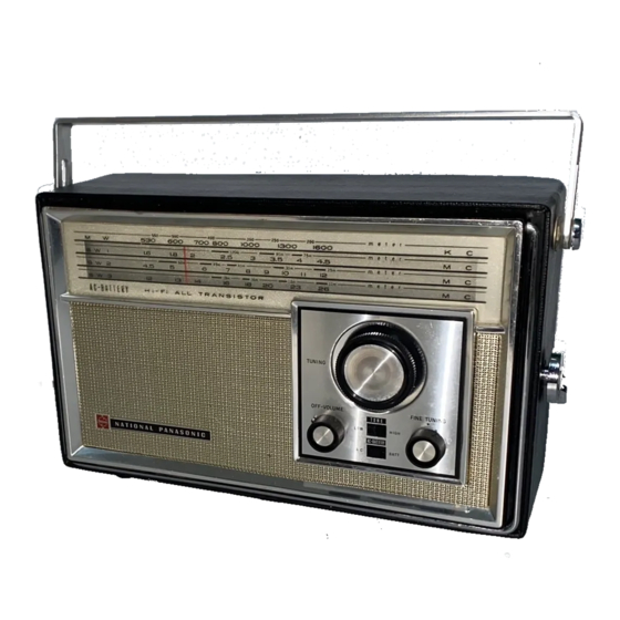
4. BAND PORTABLE
RADIO
_—
R- A4iB
SPECIFICATIONS
_ Frequency Range: |
MW.
525~1605 kHz (571~187m)
SW1 1.6~4.5 MHz (187~66.7m)
SW2
4.5~12 MHz (66.7~25.0m) .
SW3 12~26.1 MHz (25.0~11. om)
_ Intermediate Frequency:
~ 455 kHz ©
Sensitivity:
MW
30znV/m fot 50mW Output
SW1 30. pV/m for 50mW
Output
SW2 30nV/m for 50mW
Output
SW3 30nV/m for 50mW Output
Power Output:
TW
Maximum
Power Source:
-
AC 110V/220V 50-60Hz or
_ 6V (Four "D'"' Size Pashight
Batteries).
(NATIONAL UM-1
or equivalent) -
Power Consumption:
—
AW (AC Only)
Speaker:
10cm (4°) PM Dynamic Speaker
Dimensions:
|
ao
296(Wide) x 186(High) x 99. 5(Deep)mm
ie
|
(1136"° x 75%" x 324")
_ Weight:
|
_ 2kg. (4 Ib. 6.5 oz.) without batteries
_ Impedance:
Speaker - 82a
EI TO REMOVE
CHASSIS
. Remove four (4) control knobs from cabinet.
the lower part of the back cover.
. Remove four (4) red chassis cover screws.
. Pull out plugs.
figure.
Oo
Taw
N=
phono jack and AC cord from cabinet.
7. To reassemble, reverse the above procedure.
Note:
When mounting fine tuning knob, set red marking of the fine tun-
ing shaft facing up and insert fine tuning knob onto the shaft, set-
ting knobs dot to the center of red marking.
'Red Screw No.1_
Red Screw No.2
©
Red Screw No.3
(XTNSDIOER)
iokbin: rhaaale
(XTN3D10B8R)
Red Screw No.4
"Red Screw No
'Red S&r¢w No.6
(XTN3DI0BR)
ss (XTNGDIOBR)
~ = — — — S — S = « ( X
NCR)
<EXPORT DIVISIOND
MATSUSHITA
ELECTRIC TRADING CO., LTD.
P.O. Box 288 Central, Osaka, Japan
. Open the cabinet back cover by removing the two hooks on |
. Remove six (6) red chassis screws, nos. 1~6, as lustrated in
. To remove chassis completely, unsolder lead wires to 'speaker.: 3
battery, EXT. antenna & earth terminals and remove meswenene.
Earphone Jack - 890
Phono Jack - 470ka
th
1. Remove dial back plate.
2. Dial cord length i is 130cm (51 3° a
3. Tuning gang is positioned at minimum capacity.
4. Arrows (1~9) indicate correct order and direction of
installation dial cord.
. Cement dial cord ends.
on
1 TO MOUNT DIAL POINTER |
|.
Set tuning gang fully closed position.
2. Set dial pointer to start point of dial back plate.
3. Attach dial cord to dial pointer.
(oO)
(e)
Pulley
Cord
Pulley
6
Ns
7
Ce
3 turns
_
OON
Cone
=
:
9
Pa
)) / Tuning Shalt
|
f
7
/
tf
i
{©
MATSUSHITA ELECTRIC INDUSTRIAL CO., LTD.
RADIO and STEREO
DIVISION
DIAL CORD INSTALLATION GUIDE
S
Advertisement


Need help?
Do you have a question about the NATIONAL PANASONIC R-441B and is the answer not in the manual?
Questions and answers