Table of Contents
Advertisement
TABLE OF CONTENTS
1 Safety Precautions----------------------------------------------- 3
1.1. General Guidelines---------------------------------------- 3
1.2. Protection Circuitry ---------------------------------------- 3
1.3. Safety Part Information----------------------------------- 3
2 Warning -------------------------------------------------------------- 4
to Electrostatically Sensitive (ES) Devices---------- 4
3 Specifications ----------------------------------------------------- 6
4 Location of Controls and Components ------------------- 7
4.1. Listening to Radio (FM, MW, SW1, SW2) ----------- 7
4.3. Playing from USB device -------------------------------- 9
5 Installation Instructions ---------------------------------------10
5.1. Connections------------------------------------------------10
6 Disassembly and Assembly Instructions ---------------11
6.1. Disassembly flow chart----------------------------------12
6.2. Types of Screws ------------------------------------------12
6.3. Main Parts Location Diagram--------------------------12
6.4. Disassembly of Rear Cabinet Block -----------------13
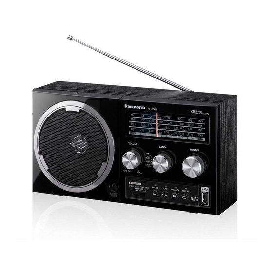
FM-MW-SW1-SW2 Portable Radio
Model No.
Product Color : (K)...Black Type
PAGE
6.5. Disassembly of Battery P.C.B. ------------------------ 14
6.6. Disassembly of Jack P.C.B. --------------------------- 15
6.7. Disassembly of Front Cabinet Block ---------------- 16
6.8. Disassembly of Speaker Unit ------------------------- 16
6.9. Disassembly of Tuner P.C.B.-------------------------- 17
6.10. Disassembly of USB P.C.B. --------------------------- 19
7 Measurements and Adjustments (Tuner) --------------- 21
7.1. FM IF Alignment------------------------------------------ 21
7.2. RF Alignment---------------------------------------------- 22
8 Wiring Connection Diagram--------------------------------- 25
9 Schematic Diagram -------------------------------------------- 27
9.1. Schematic Diagram Notes ----------------------------- 27
9.2. TUNER CIRCUIT (1/2) --------------------------------- 29
9.3. TUNER CIRCUIT (2/2) --------------------------------- 30
9.4. USB CIRCUIT--------------------------------------------- 31
9.5. BATTERY & JACK CIRCUIT -------------------------- 32
10 Printed Circuit Board ------------------------------------------ 33
10.1. TUNER P.C.B. -------------------------------------------- 33
10.2. USB, BATTERY, JACK & SUPPORT P.C.B. ------ 34
11 Appendix Information of Schematic Diagram --------- 35
© Panasonic Corporation 2012. All rights reserved.
Unauthorized copying and distribution is a violation of
law.
RF-800UGA
RF-800UGS
PSG1210003CE
PAGE
Advertisement
Table of Contents

Related Manuals for Panasonic RF-800UGA


Summary of Contents for Panasonic RF-800UGA
-
Page 1: Table Of Contents
10.2. USB, BATTERY, JACK & SUPPORT P.C.B. ------ 34 6.4. Disassembly of Rear Cabinet Block -----------------13 11 Appendix Information of Schematic Diagram --------- 35 © Panasonic Corporation 2012. All rights reserved. Unauthorized copying and distribution is a violation of law. - Page 2 11.1. Illustration of IC’s, Transistors and Diodes -------- 35 11.2. Terminal Function of IC --------------------------------- 36 12 Exploded View and Replacement Parts List ----------- 37 12.1. Exploded View and Mechanical replacement Parts List --------------------------------------------------- 37 12.2. Electrical Replacement Parts List -------------------- 40...
-
Page 3: Safety Precautions
1 Safety Precautions 1.1. General Guidelines 1. When servicing, observe the original lead dress. If a short circuit is found, replace all parts which have been overheated or damaged by the short circuit. 2. After servicing, see to it that all the protective devices such as insulation barriers, insulation papers shields are properly installed. -
Page 4: Warning
2 Warning 2.1. Prevention of Electro Static Discharge (ESD) to Electrostatically Sensi- tive (ES) Devices Some semiconductor (solid state) devices can be damaged easily by static electricity. Such components commonly are called Elec- trostatically Sensitive (ES) Devices. Examples of typical ES devices are integrated circuits and some field-effect transistors and semiconductor “chip”... -
Page 5: Service Caution Based On Legal Restrictions
2.2. Service caution based on Legal restrictions 2.2.1. General description about Lead Free Solder (PbF) The lead free solder has been used in the mounting process of all electrical components on the printed circuit boards used for this equipment in considering the globally environmental conservation. The normal solder is the alloy of tin (Sn) and lead (Pb). -
Page 6: Specifications
3 Specifications Power requirement Battery DC 6 V, (4 x R20/LR20, D) Battery life (Manganese) Radio: 80 hours USB: 25 hours DC IN DC 6 V, 1.2 A, Power output (DC 6 V, USB) 2.5 W (Max.) Radio frequency range 87.5 MHz to 108.0 MHz (3.43 m to 2.78 m) 520 kHz to 1610 kHz... -
Page 7: Location Of Controls And Components
4 Location of Controls and Components 4.1. Listening to Radio (FM, MW, SW1, SW2) -
Page 8: Playing From Music Device Using Music Port
4.2. Playing from Music device using music port... -
Page 9: Playing From Usb Device
4.3. Playing from USB device Compatibility USB • For compatibility of USB please refer to Operating Instructions. -
Page 10: Installation Instructions
5 Installation Instructions 5.1. Connections... -
Page 11: Disassembly And Assembly Instructions
6 Disassembly and Assembly Instructions Caution Note: • This section describes the disassembly and/or assembly procedures for all major printed circuit boards & main compo- nents for the unit. (You may refer to the section of “Main components and P.C.B Locations” as described in the service manual) •... -
Page 12: Disassembly Flow Chart
6.1. Disassembly flow chart The following chart is the procedure for disassembling the casing and inside parts for internal inspection when carrying out the ser- vicing. To assemble the unit, reverse the steps shown in the chart below. 6.2. Types of Screws 6.3. -
Page 13: Disassembly Of Rear Cabinet Block
6.4. Disassembly of Rear Cabinet Step 3 : Slightly lift up the Rear Cabinet Block. Step 4 : Detach 2P cable at the connector (CN1) on the Tuner Block P.C.B.. Step 1 : Press the OPEN button to open the Battery Cover Assembly. -
Page 14: Disassembly Of Battery P.c.b
6.5. Disassembly of Battery P.C.B. Step 4 : Remove the Battery P.C.B.. Caution : During assembling, inserted the 2P Cable into • Refer to “Disassembly of Rear Cabinet Block”. the opening of Rear Cabinet Block as diagram shown. Ensure the Battery P.C.B. is seated properly into the slots. Step 1 : Release the catch. -
Page 15: Disassembly Of Jack P.c.b
6.6. Disassembly of Jack P.C.B. Step 3 : Remove the Support P.C.B.. Caution 1 : Keep the Support P.C.B. in safe place and place • Refer to “Disassembly of Rear Cabinet Block”. it back during assembling. Step 1 : Release the 6P Cable from the slots. Caution : During assembling, ensure that the 6P cable is properly inserted into the slots. -
Page 16: Disassembly Of Front Cabinet Block
6.7. Disassembly of Front Cabinet 6.8. Disassembly of Speaker Unit Block • Refer to “Disassembly of Rear Cabinet Block”. • Refer to “Disassembly of Front Cabinet Block”. • Refer to “Disassembly of Rear Cabinet Block”. Step 1 : Remove 4 screws. Step 1 : Remove 2 screws. -
Page 17: Disassembly Of Tuner P.c.b
6.9. Disassembly of Tuner P.C.B. Step 2 : Remove the Volume Knob. Caution : Keep the Volume Knob in safe place and place it • Refer to “Disassembly of Rear Cabinet Block”. back during assembling. • Refer to “Disassembly of Front Cabinet Block”. Preparation before assembling: Turn the Dial Pointer to the end position. - Page 18 Step 4 : Detach 2P cable at the connector (CN104) on the Step 7 : Remove the Tuner P.C.B.. Tuner P.C.B.. Step 5 : Detach 2P cable at the connector (CN105) on the Tuner P.C.B.. Step 6 : Detach 6P cable at the connector (CN101) on the Tuner P.C.B..
-
Page 19: Disassembly Of Usb P.c.b
Caution : Ensure that the Tuner P.C.B. is fully seated on to 6.10. Disassembly of USB P.C.B. the guide as shown. • Refer to “Disassembly of Rear Cabinet Block”. • Refer to “Disassembly of Front Cabinet Block”. • Refer to “Disassembly of Tuner P.C.B.”. Step 1 : Remove the Band Spring. - Page 20 Step 3 : Turn the Band Rotary Lever clockwise towards to the Step 5 : Remove 5 screws. guide as shown. Step 6 : Remove the USB P.C.B.. Step 4 : Lift up to remove the Band Rotary Lever. Caution : During assembling, align the guide of the Band Rotary Lever with the rib of the Front Cabinet Block .
-
Page 21: Measurements And Adjustments (Tuner)
7 Measurements and Adjustments (Tuner) 7.1. FM IF Alignment 7.1.1. Setting up for FM IF Alignment READ CAREFULLY BEFORE ATTEMPTING ALIGNMENT 1. Set selector switch to FM, MW, SW1 or SW2. 2. Set volume level to maximum. 3. Output of signal. ALIGNMENT: MGS - WS42 - 01 INSTRUMENT: IF SWEEMAR SCOPE SIGNAL INJETION I/P: TP 4 (SIGNAL), TP 6 (GND) -
Page 22: Rf Alignment
7.2. RF Alignment 7.2.1. Setting up for RF Alignment ALIGNMENT STANDARD : MGS - WS41 - 03, 04, 05 (For AM) : MGS - WS42 - 02, 03 (For FM) INSTRUMENT : AM AND FM SWEEMAR SCOPE 7.2.2. Method of signal injection and O/P test point BAND MW, SW1 SIGNAL INPUT... - Page 23 7.2.3. Alignment frequencies BAND OSC BLOCK LOCATION (RANGE ALIGNMENT) ANT BLOCK LOCATION (SENS ALIGNMENT) FREQUENCY (GA)..86,2 MHz (GA)..109,2 MHz 106 MHz (GS)..87,40 MHz (GS)..108,30 MHz CR-NO CT1 - 4 CT1-3 FREQUENCY (GA)..511 KHz (GA)..1650 KHz 550 KHz 1500 KHz (GS)..520 KHz (GS)..1640 KHz CR-NO CT1-2...
-
Page 25: Wiring Connection Diagram
(TO SPEAKER UNIT) W101* W104* USB P.C.B. DC 6V (4 x R20/LR20, D) W105* SOLDER SIDE JK101 USB101 SOLDER SIDE USB PORT MUSIC PORT HEADPHONE DC IN JACK P.C.B. RF-800UGA/GS NOTE "*" REF IS FOR INDICATION ONLY WIRING CONNECTION DIAGRAM... -
Page 27: Schematic Diagram
9 Schematic Diagram 9.1. Schematic Diagram Notes (All schematic diagrams may be modified at any time with the development of new technology) Notes: S101: REW switch S102: PLAY/PAUSE switch S103: FF switch S104: REPEAT switch SW1: SELECTOR switch. SW101: FUNCTION switch. •... -
Page 29: Tuner Circuit (1/2)
0.022 RL0N2B108-C 360P RLVN5D036-C SW1_3 SW1_7 SW1_5 C1BA00000481 AM / FM RADIO RLI4B153-C RL0N3B91-C SW1_2 1500P 0.01 SW1 ANT RLQY15G5-M 0.01 SW1_8 RLQY30S4W 330K 0.01 RL0N3B95-C SW1_4 CF22 4700P RLFNLTZ455JL 0.01 RLAN3B44-C KTC3192-0-AT AMPLIFIER 0.022 0.01 0.01 RF-800UGA/GS TUNER CIRCUIT... - Page 30 B- BATT AUDIO GND IN SCHEMATIC VCC DC IN IN SCHEMATIC DIAGRAM - 4 DIAGRAM - 3 USBGND AGND IGND BATTERY CIRCUIT (W1*) IN SCHEMATIC DIAGRAM - 4 RF-800UGA/GS TUNER CIRCUIT NOTE: “ * ” REF IS FOR INDICATION ONLY...
-
Page 31: Usb Circuit
+1.8V DRIVE SWITCH W105* C0EBE0000124 C119 TUNER CIRCUIT RESET AUDIO GND 10V47 S101 (CN105) C141 10V47 IN SCHEMATIC DIAGRAM - 2 S102 S103 D107 PLAY B0JCMC000006 /PAUSE R101 R138 100K RF-800UGA/GS NOTE: “ * ” REF IS FOR INDICATION ONLY CIRCUIT... -
Page 32: Battery & Jack Circuit
SP - SP + TUNER CIRCUIT B+ BATT (CN2) B- BATT IN SCHEMATIC VCC DC IN DC IN B0EAKM000103 DIAGRAM - 2 6V 100A (8V PROTECTION) RF-800UGA/GS NOTE: “ * ” REF IS FOR INDICATION ONLY BATTERY / JACK CIRCUIT... -
Page 33: Printed Circuit Board
W5B* 0070AA-1 0070AA-1 TUNING CT12 W3B* CT11 W3A* BAND W5A* CN104 L32* VOLUME CF21 W4A* CF24 CF23 CN105 2 -B 1 +B CF22 W4B* CN101 (TO SPEAKER) SELECTOR NOTE: " * " REF IS FOR INDICATION ONLY RF-800UGA/GS TUNER P.C.B. -
Page 34: Usb, Battery, Jack & Support P.c.b
JACK P.C.B. (REPN0070AD)...GA (REPN0070BC)...GS (REPN0070BD)...GS 0070AD-1 0070AD-1 0070AC-1 0070AC-1 HEADPHONE DC IN DC 6V (4 x R20/LR20, D) SUPPORT P.C.B. (REPN0070AE)...GA (REPN0070BE)...GS 0070AE-1 0070AE-1 NOTE: " * " REF IS FOR INDICATION ONLY RF-800UGA/GS USB / BATTERY / JACK / SUPPORT P.C.B. -
Page 35: Appendix Information Of Schematic Diagram
11 Appendix Information of Schematic Diagram 11.1. Illustration of IC’s, Transistors and Diodes C1AB00004021 (64P) C0CBABE00023 RSB12JS2T2R C0EBE0000124 C1BA00000424 C1BA00000481 B1ABCF000176 B1CFQD000011 KTC3192-0-AT B0EAKM000103 B3AAA0000608 B0JCMC000006 B1GDCFJJ0047 B1CHPB000005 B3ACA0000220 SLR325MCT31W Cathode Cathode Anode Anode... -
Page 36: Terminal Function Of Ic
11.2. Terminal Function of IC 11.2.1. IC101 (C1AB00004021) USB AUDIO DECODER Pin No. Mark Function LED_REPEAT Repeat LED Pin No. Mark Function TEST13 Pull up to 3.3V system power supply RESETX ”H: Release Reset, L: Reset” DVDD_M1 Connect to bypass condenser. SEL_SLAVE ”H: Stand Alone, L: Slave”... -
Page 37: Exploded View And Replacement Parts List
12.1.1. Cabinet Parts Location (BATTERY P.C.B.) (JACK P.C.B.) (SUPPORT P.C.B.) (TUNER P.C.B) CN104 CN105 CN101 *W101 *W104 *W105 (USB P.C.B.) JK101 S101 SW101 S102 USB101 S103 S104 RF-800UGA/GS-K NOTE: " * " PART IS NOT SUPPLIED/REF IS FOR INDICATION ONLY. CABINET DRAWINGS... - Page 38 12.1.2. Packaging O/I BOOK RF-800UGA/GS F R O N POLYFOAM (LEFT) POLYFOAM (RIGHT) RF-800UGA/GS-K PACKAGING DRAWINGS IPSG1210...
- Page 39 12.1.3. Mechanical Repacement Parts List Safety Ref. No. Part No. Part Name & Qty Remarks Description Safety Ref. No. Part No. Part Name & Qty Remarks RKSN0018A-K BACK CABINET Description RMBX0002-3 BATTERY SPRING RMEN0012 BAND SPRING CABINET AND RMGN0014 RUBBER LEG CHASSIS RMLN0008-X BAND ROTARY...
-
Page 40: Electrical Replacement Parts List
12.2. Electrical Replacement Parts List Safety Ref. No. Part No. Part Name & Qty Remarks Description Safety Ref. No. Part No. Part Name & Qty Remarks KTC3192-0-AT TRANSISTOR Description B1ABCF000176 TRANSISTOR B1ABCF000176 TRANSISTOR PRINTED CIRCUIT Q103 B1CFQD000011 TRANSISTOR BOARDS Q104 B1CFQD000011 TRANSISTOR Q105... - Page 41 Safety Ref. No. Part No. Part Name & Qty Remarks Safety Ref. No. Part No. Part Name & Qty Remarks Description Description RCV4RCT0V-T VARIABLE CAPACI- L108 ERJ3GEY0R00V 1/10W ERJ3GEY0R00V 1/10W ERJ3GEY0R00V 1/10W CONNECTORS W201 ERJ3GEY0R00V 1/10W W202 D0GDR00JA055 1/8W K1KA02AA0180 2P CONNECTOR W203 ERJ3GEY0R00V...
- Page 42 Safety Ref. No. Part No. Part Name & Qty Remarks Safety Ref. No. Part No. Part Name & Qty Remarks Description Description R126 ERJ3GEYJ220V 1/10W C106 F1H1H120A841 12pF R127 ERJ3GEYJ220V 1/10W C107 F1H1H120A841 12pF R128 ERJ3GEYJ333V 1/10W C108 F1J1A106A024 10uF R129 ERJ3GEYJ104V 100K...
Need help?
Do you have a question about the RF-800UGA and is the answer not in the manual?
Questions and answers