Table of Contents
Advertisement
Quick Links
Advertisement
Table of Contents

Related Manuals for AYRO VANISH


Summary of Contents for AYRO VANISH
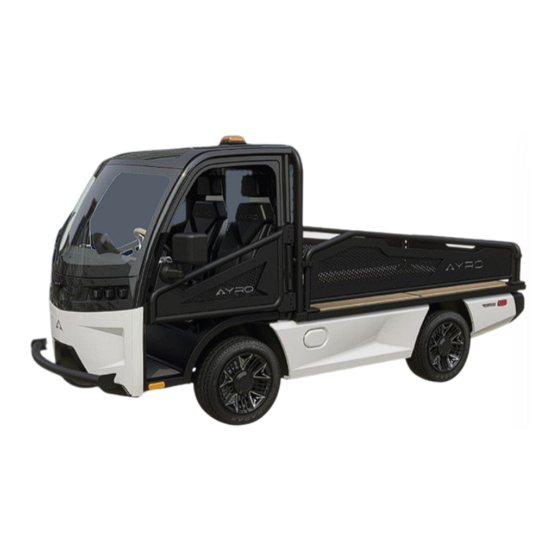
- Page 1 INTRO Low - Speed Electric Vehicle SERVICE MANUAL Page 1 of 48...
-
Page 2: Table Of Contents
CONTENTS Table of Contents INTRODUCTION ..........................5 Applicability ..........................5 AYRO Service Department ......................5 For Reference Only ........................6 Compliance (NHTSA) ........................6 Applicability ..........................6 GENERAL SAFETY ..........................6 CABIN ..............................7 Fascia and Trim ..........................7 3.1.1 Middle Front Fascia ...................... - Page 3 CONTENTS Alignment ........................... 17 SUSPENSION ............................ 18 Front ............................18 5.1.1 Upper Control Arm ......................18 5.1.2 Lower Control Arm ......................18 5.1.3 Coil-Over Shock ........................ 19 5.1.4 Wheel Hub ......................... 19 Rear ............................. 20 5.2.1 Leaf Springs ........................20 Motor Specifications ........................
- Page 4 CONTENTS Heating Element ....................... 30 9.2.2 Common Issues with AC system ..................... 30 COOLING SYSTEM ........................32 10.1 Radiator ............................32 10.1.1 Removal ..........................33 Installation ......................... 33 10.1.2 10.1.3 Removal ..........................34 Installation ......................... 34 10.1.4 Battery Charging & Maintenance....................35 11.1 Battery Handling Precautions....................
-
Page 5: Introduction
The purpose of this Service Manual is to present information you require as an authorized AYRO service representative. This Manual provides the instructions and guidance needed for the maintenance or repair of the AYRO Vanish Low Speed Electric Vehicle models (LSV and Non-LSV). -
Page 6: For Reference Only
Manual and the vehicle. Descriptions, depictions, and/or procedures in this document are intended for reference only. No liability can be accepted for omissions or inaccuracies. AYRO, Inc. reserves the right to make changes at any time, without notice and without incurring any obligation to make the same or similar changes to vehicles previously manufactured. -
Page 7: Cabin
CABIN 3 CABIN 3.1 Fascia and Trim Tools, Equipment, Materials: • Metric Allen hex wrench • Metric wrench (typically 10 mm) 3.1.1 Middle Front Fascia Tools, Equipment, Materials: • Metric Allen hex wrench (typically 2.5 mm) • Metric wrench (typically 10 mm) Removal 1. -
Page 8: Lower Fascia
CABIN 4. Pop out the upper fascia and remove the windshield sprayer hose from the fitting on the inside of the fascia panel. Installation 1. Attach the windshield sprayer hose to the fitting on the inside of the panel then insert the upper fascia into position by putting the top lip of the fascia under the windshield. -
Page 9: Interior Trim
CABIN 3.1.5 Interior Trim Removal 1. Remove middle front fascia (Ref. 3.1.1). 2. Remove steering wheel (Ref. 4.3) 3. Remove upper column cover (Ref 3.2) 4. Remove Ignition switch. (Ref. 3.2.1) 5. Remove the four (4) nuts that secure the trim panel to the dash using a wrench; the outer two (2) nuts have a trim retaining bracket that will need to be removed as well. -
Page 10: Mirrors
CABIN 3.1.7 Mirrors Figure 2: Mirrors with 2 Bolts Tools, Equipment, Materials: • Metric Allen hex wrench (typically 6 mm) Removal 1. Remove magnetic cover from the mirror hinge. Page 10 of 48... -
Page 11: Wiper Arm
CABIN 2. Remove 2 mounting bolts securing the mirror hinge to the cab frame using a 6 mm Allen wrench. Hold onto or secure the mirror so it does not fall or sustain damage when removing the last bolt. Installation 1. -
Page 12: Wiper Motor/Wiper Mechanism
CABIN • Metric Allen hex wrench (typically 5 mm) • Metric wrench (typically 10 mm) Removal 1. Remove upper fascia (Ref. 3.1.2) 2. Disconnect the wiper motor connectors from the cab harness. 3. Remove the two (2) bolts that secure the wiper motor assembly to the firewall bracket using an Allen wrench for the bolts and a metric wrench on the nut. -
Page 13: Body
CABIN Removal 1. Remove mirrors. (Ref. 3.1.7) 2. Remove four (4) screws from the lower dash using a metric Allen wrench. 3. Remove the lower dash. 3.3 Body 3.3.1 Long Side Skirt Tools, Equipment, Materials: Extraction tool for plastic trim rivet clips •... - Page 14 CABIN 2. Disconnect the 6-pin Deutsch connector that joins the chassis harness to the bumper harness. 3. Disconnect the back-up camera cable connection. 4. Remove the two (2) bolts that secure the bumper bracket to the chassis on the driver side using a metric Allen hex wrench;...
-
Page 15: Steering System
STEERING SYSTEM 4 STEERING SYSTEM 4.1 Electric Power Steering (EPS) Tools, Equipment, Materials: • Metric wrench (typically 14 mm) Removal 1. Disconnect the two connectors that are inserted into the EPS motor. 2. Loosen the two u-joints that are attached to the input and output shafts of the EPS motor. -
Page 16: Steering Wheel
STEERING SYSTEM 2. Insert the tie rod into the wheel hub and secure it with the tie rod nut using a wrench. Tighten until seated. 3. Attach the u-joint to the rack and pinion and tighten the u-joint bolt with a wrench. 4. -
Page 17: Tie Rods
STEERING SYSTEM 4.5 Tie Rods Tools, Equipment, Materials: • Metric wrench (typically 17 mm) • Marker or tape Removal 1. Lift the vehicle and place it on jackstands. 2. Remove the tire. (Ref. 8.1) 3. Loosen the jam nut on the tie rod. 4. -
Page 18: Suspension
JACK POINTS 5 SUSPENSION 5.1 Front 5.1.1 Upper Control Arm Tools, Equipment, Materials: • Metric wrenches (typically 13, 17, and 18 mm) Removal 1. Remove Wheel (Ref. 8.1) 2. Remove the coil-over shock. (Reference 5.1.3) 3. Disconnect brake line retaining mount bolt using a wrench. 4. -
Page 19: Coil-Over Shock
SUSPENSION Installation 1. Install the lower control arm using the two mounting bolts, thread on the lock nuts finger tight. Do not tighten. 2. Attach the lower ball joint to the wheel hub and secure with the lower ball joint nut. Use wrench and tighten until seated. -
Page 20: Rear
SUSPENSION 4. Remove shock (Ref. 5.1.3) 5. Remove the cotter pin from the upper ball joint and remove the castle nut with a wrench. 6. Separate the ball joint from the wheel hub. 7. Remove the lower ball joint nut using a wrench and separate the lower ball joint from the wheel hub. -
Page 21: Motor Specifications
SUSPENSION Installation 1. Install the new leaf spring using the leaf spring hanger bolts. Tighten with a wrench until the bushing starts to compress. 2. Align the leaf springs with the leaf spring retaining bolt and secure with the retaining nut. Tighten until the bushing starts to compress. -
Page 22: Jack Points
JACK POINTS 6 JACK POINTS Figure 5: Jack Points under Subframe (front) and Axle (rear) Page 22 of 48... -
Page 23: Wheels/Tires
7. Remove the wheel. 1.2 Tire rotation The proprietary Vanish Schlägernull tires are directional, so the proper rotation procedure is to move the front driver tire to the rear driver side and move the rear driver side to the front driver side. -
Page 24: Brakes
BRAKES 8 BRAKES 8.1 Verifying Brake Fluid Levels Remove the front face cover of the vehicle to expose the brake fluid reservoir. The reservoir is located on the front driver’s side. If the fluid level in the reservoir is less than MAX, remove the cap and add brake fluid. - Page 25 BRAKES 5. Bleed Valves- Beginning at the rear-passenger brake location, open the rubber cover of the bleed valve. Attach one end of the vinyl tube to the bleed valve and place the other end of the vinyl tube into the bottle/jar. Request that the 2nd person ‘pump’ the brakes 5- 10x, and then hold in the fully pressed position.
-
Page 26: Brakes & Rotors
BRAKES 8.3 Brakes & Rotors Figure 6: Brake Assembly, top view Figure 7: Brake Assembly, outside view 8.3.1 Brake Pads Tools, Equipment, Materials • Metric wrenches (rear typically 13 mm, front typically 14 mm) • C-clamp Replacement 1. Remove Wheel(s) (Ref. 8.1) and master cylinder cap. 2. -
Page 27: Calipers
BRAKES Rear 1. Remove Wheel (Ref. Wheels & Tires 8.1). 2. Remove (2) 13 mm caliper housing bolts, starting with the bottom, then the top. 3. Place the caliper aside, making sure it is properly secured. Do not let the calipers hang by brake line. - Page 28 BRAKES 2. Remove connectors from the brake pressure sensor that is on the master cylinder. 3. Remove middle front fascia. (Ref. 3.1.1) 4. Remove upper fascia. (Ref. 3.1.2) 5. Remove the brake lines from the master cylinder using an 11 mm wrench on the braided line fitting and a 14 mm wrench on the union.
-
Page 29: Climate Control System
CLIMATE CONTROL SYSTEM 9 CLIMATE CONTROL SYSTEM 9.1 A/C System Inspect all components before servicing. Follow best practices for troubleshooting the air conditioning system. 9.1.1 Compressor Tools: • Metric wrenches (typically 13, 14, 22, and 27 mm) • Metric Allen hex wrench (typically 5 mm) 9.1.2 Refrigerant and Fluids If so equipped, the optional air conditioning system uses R-1234yf refrigerant, which offers superior environmental performance. -
Page 30: Manifold And Hoses
CLIMATE CONTROL SYSTEM Removal/Installation Remove the condenser from the mounting using a box wrench. Remove hose fittings using box wrenches. 9.1.4 Manifold and Hoses Tools: • Metric wrench (typically 13 mm) 9.1.5 High/Low pressure switches Tools, Equipment, Materials: • Metric wrench (typically 22 mm) Removal/Installation Remove pressure switch with a wrench and disconnect wiring. - Page 31 CLIMATE CONTROL SYSTEM • Restricted expansion device or refrigerant charging hose Dirty or restricted air flow over condenser • Restricted air flow over evaporator • • Clutch not engaging • Failed compressor or compressor clutch • Failed blower motor or blower motor resistor •...
-
Page 32: Cooling System
COOLING SYSTEM 10 COOLING SYSTEM Tools, Equipment, Materials • Metric wrench (typically 13 mm) • Metric Allen hex key (typically 10 mm) • Metric Allen hex key (typically (4 mm) • Pliers • Drip pan 10.1 Radiator Figure 8: Radiator Top View Figure 9: Radiator Front View Page 32 of 48... -
Page 33: Removal
COOLING SYSTEM 10.1.1 Removal 1. Remove the hose clamps for the upper and lower radiator hoses using pliers. Make sure to have a drip pan to collect the coolant as it drains out of the radiator. Be sure to plug or clamp the coolant hoses. -
Page 34: Removal
COOLING SYSTEM 10.2 Cooling Pumps 10.1.3 Removal 1. Remove the hose clamps securing the input and output hoses on the coolant pump using pliers. Remove the hoses from the coolant pump. Make sure you have a drip pan to collect any coolant that may leak from the pump or hoses. Be sure to plug or clamp the coolant hoses. -
Page 35: Battery Charging & Maintenance
Do not charge batteries in a non-ventilated enclosed area or near flammable materials. The lithium-ion batteries in your Vanish will not accept a charge unless internal battery temperatures are at or above 32 deg F (0 deg C). When the ambient temperature is at or below 32 deg F (0 deg C), the vehicle must be moved to a location where the battery pack can warm up to 32 deg F (0 deg C) or higher to receive a charge. - Page 36 BATTERY CHARGING AND MAINTENANCE 11.1.3 On-Board Charger: The on-board battery charger is located behind the driver side panel. The state of charge of the batteries is displayed in the vehicle’s driver information display. When the vehicle will not be used for an extended period, plug the charging cable into the vehicle.
- Page 37 BATTERY CHARGING AND MAINTENANCE 11.4 Charging Instructions (Standard 110/120VAC outlet): Open the receptacle cover and prepare to engage the standard equipped charging cable that came with the vehicle. A. Plug the (J1772) plug interface into the charging receptacle (driver side access panel) and ensure a solid fit.
-
Page 38: Payload Configurations
PAYLOAD CONFIGURATIONS 12 PAYLOAD CONFIGURATIONS • Flatbed • Light Duty Pickup with Triple Fold-Down Gates • Van Box • Powered Van Box • Roll-On / Roll-Off • Trailer Hitch Page 38 of 48... -
Page 39: Diagrams/Layouts (Fuses, Wiring)
LAYOUTS (FUSE BOX, WIRING) 13 DIAGRAMS/LAYOUTS (FUSES, WIRING) 13.1 Fuse Box Figure 2 Vanish Fuse Box and Relay Layout Page 39 of 48... -
Page 40: Wiring
94-2010-0000 HARNESS, VANISH, HV PDU TO DC-DC 94-2011-0000 HARNESS, VANISH, HV PDU TO INV POS 94-2012-0000 HARNESS, VANISH, HV PDU TO INV NEG 94-2013-0000 HARNESS, VANISH, HV PDU TO HVAC PTC HTR 94-2014-0000 HARNESS, VANISH, HV PDU TO HVAC COMP 94-2015-0000 HARNESS, VANISH, EPAS POWER... -
Page 41: Spare Parts List
SPARE PARTS LIST SPARE PARTS LIST 14.1 Batteries and Charging System BATTERY, 12V, 31 AH, BRAILLE (starting, cabin accessories) 44-2007-0000 CABLE, CHARGING, DUOSIDA 41-2024-0000 Page 41 of 48... -
Page 42: Body
SPARE PARTS LIST 14.2 Body SIDE MIRRORS 88-2041-7200 14.3 Brakes, Disc BRAKE PADS (set) 88-2007-0030 ROTOR 88-2007-0020 Page 42 of 48... - Page 43 SPARE PARTS LIST CALIPERS Left 88-2007-000L Right 88-2007-000R MASTER CYLINDER, CENTRIC RIGHT, WITH FLUID SENSOR 88-2035-0003 Page 43 of 48...
-
Page 44: Coolant System
SPARE PARTS LIST 14.4 Coolant System Coolant Pump 44-2037-0023 14.5 Suspension, Front & Rear STEERING SHAFT, UPPER SHAFT ASSY 88-2006-7003 STEERING SHAFT, LOWER SHAFT ASSY 88-2006-7004 Page 44 of 48... - Page 45 SPARE PARTS LIST SHOCK, COILOVER, FRONT SUSPENSION, NON-ADJUST 88-2026-0001 Page 45 of 48...
-
Page 46: Wheel End Components
SPARE PARTS LIST 14.7 Wheel End Components TIRES, AYRO SERIES X, SCHLAGERNULL 88-2040-0000 WHEEL, AYRO CUSTOM 88-2030-0000 14.8 Windshield WINDSHIELD, FRONT, AYRO Z 68-2000-0000 14.9 Windshield Wiper & Washer system WINDSHIELD WIPER BLADE 88-2060-0020 Page 46 of 48... - Page 47 AYRO, Inc. 900 E. Old Settlers Boulevard, Suite 100 Round Rock, TX 78664 USA Tel: +1 512-994-4917 (U.S.A. Domestic and International) Email support@ayro.com PN 19-0005-0000 ©2023 AYRO, INC. Page 47 of 48...
- Page 48 Page 48 of 48...
Need help?
Do you have a question about the VANISH and is the answer not in the manual?
Questions and answers