
Related Manuals for Actox ACBU011

Summary of Contents for Actox ACBU011
- Page 1 ACBU011/ACLU011 User Manual ACBU011 / ACLU011 REDUNDANCY CONTROLLER USER MANUAL Page 1 of 21...
-
Page 2: Table Of Contents
ACBU011/ACLU011 User Manual Table of contents Specifications ..................3 Block Overview ..................4 III. 19 pin connector for a PC / Laptop ............5 Connector for a Waveguide Switch ............7 ... -
Page 3: Specifications
ACBU011/ACLU011 User Manual Redundancy Controller Specifications Redundancy Input Power 12‐55 V 5 A Maximum Load Current Power Consumption 10 W Load Current Analizer Yes Dimentions 214mm x 188mm x 56.5mm Weight 2.6 kg Operating Temperature ‐40°C to + 70°C Storage Temperature Range ‐40°C to + 80°C Input Interface N‐Type or F‐type Internal Reference Yes (Autodetect) Certain Internal Reference stability ±3*10^‐8 1 Hz <‐85 dBC/Hz 10 Hz <‐115 dBC/Hz Internal Reference Phase Noice 100 Hz <‐140 dBC/Hz 1000 Hz <‐150 dBC/Hz 10000 Hz <‐150 dBC/Hz ... -
Page 4: Block Overview
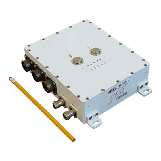
ACBU011/ACLU011 User Manual Block Overview The appearance of the Redundancy Controller and it`s connectors are displayed on figure 1.1. Figure 1.1 — Redundancy Redundancy connection ports from one side: Two L-band F (or N) connectors for BUC connection provided via coaxial cable;... -
Page 5: 19 Pin Connector For A Pc / Laptop
ACBU011/ACLU011 User Manual III. 19 pin connector for a PC / Laptop Redundancy Controller connection to PC carried by cable with 19 pin female connector (fig.1) on the one side and RJ45 (fig. 2), two DB9 (fig. 3) female connectors: RS232 and RS485 on the other side. - Page 6 ACBU011/ACLU011 User Manual R75_RX GNDISO GNDISO RS485 GNDISO GNDISO GNDISO GNDISO RS232 RS232TX RS232RX Figure 2.4 — Redundancy 19 pin connector for a PC/Laptop Page 6 of 21...
-
Page 7: Connector For A Waveguide Switch
ACBU011/ACLU011 User Manual 20-pin (Unit 20-pin (Unit 19-pin Connector Pin Name Ethernet MUTE1 ALARM1 RS232_TX1 RS232_RX1 GNDISO GNDISO RS232_TX2 RS232_RX2 MUTE2 ALARM2 RX_P RX_N TX_P TX_N Figure 2.4 — Redundancy 19-pin cable to Unit 1 and Unit 2 Connector for a Waveguide Switch Redundancy Controller connection to waveguide switch carried by cable with 19 pin female connector (fig. - Page 8 ACBU011/ACLU011 User Manual From Redundancy Interface pin From Switch pin Figure 3.2 — Switch interface Page 8 of 21...
-
Page 9: Redundancy Terminal User Manual
ACBU011/ACLU011 User Manual Redundancy Terminal User Manual Run Redundancy Terminal v 1.1 on your PC, when it opened you will see next window: Figure 4.1 — Start window On the top of the window situated menu tabs. Interface – consist information about redundancy connection;... - Page 10 ACBU011/ACLU011 User Manual Figure 4.2 — Redundancy Status Window POWER SUPPLY: Redundancy power supply provides by two ways: by DC power supply (U DC1 and U DC2) and by RF connector from modem (Umodem). Function displays current income voltage and power port connection. Voltage is in OK if it’s value within acceptable limits and ERROR if voltage out of limits.
- Page 11 ACBU011/ACLU011 User Manual __________________________________________________________________ NOTE Power is calculated by multiplying the current to voltage __________________________________________________________________ ALARM STATUS: displays summary failure of BUC. ALARM STATUS is an analog signal, transmitted via M&C cable. OK if alarmed, DISABLE if unalarmed. SERIAL STATUS: displays port connection status. SERIAL STATUS is a digital signal, transmitted via M&C cable.
- Page 12 ACBU011/ACLU011 User Manual Figure 4.6 Default configurations for LNB Figure 4.5 — Default configurations for BUC Supply parameters — set here minimum/maximum parameters for voltage, power or amperage supply and waveguide switch motor voltage value: Minimum voltage – set here minimum value for Redundancy supply. This value: ...
- Page 13 ACBU011/ACLU011 User Manual Maximum Power/Ampere – set here maximum Power or Current for each BUC and LNB and must be higher than maximum power (current) value for BUC or LNB, but can’t be higher than 5 A; WS Motor Voltage – set here nominal voltage value that written in specifications for your switch device.
- Page 14 ACBU011/ACLU011 User Manual Figure 4.8 — Net Configuration window Set manually parameters you want to change and push button Send to device. In the latest version of the software you can change waveguide position. Open inset WS on the menu push button Set Position.
-
Page 15: Web Interface User Manual
ACBU011/ACLU011 User Manual Web interface user manual Web interface provided with 19 pin connector for a PC/Laptop (see fig. 2.4) Connect Redundancy controller with your PC/Laptop via Ethernet, switch on the device and open internet browser. In the address line type in IP address of your Redundancy (by default IP address: 192.168.1.249) and you will see log-in window (fig. - Page 16 ACBU011/ACLU011 User Manual Figure 6.2 — Redundancy Status page POWER SUPPLY: Redundancy power supply provides by two ways: by DC power supply (U DC1 and U DC2) and by RF connector from modem (Umodem). Function displays current income voltage and power port connection. Voltage is in OK if it’s value within acceptable limits and ERROR if voltage out of limits or...
- Page 17 ACBU011/ACLU011 User Manual this mode; You can switch this parameter on the Autodetect mode if your Redundancy has it’s own Internal reference frequency; POWER STATUS: displays power or amperage appliance of BUC. Power or Amperage is in OK if it’s value within acceptable limits and ERROR if out of limits.
- Page 18 ACBU011/ACLU011 User Manual lower than minimum power (current) value for BUC or LNB, but can’t be lower than 0.02 A; Maximum Power/Current – set here maximum Power or Current for each BUC and LNB and must be higher than maximum power (current) value for BUC or LNB, but can’t be higher than 5 A;...
-
Page 19: Snmp User Manual
ACBU011/ACLU011 User Manual VII. SNMP User Manual SNMP Configuration menu could be found in the bottom of the Web interface page. Depending on the SNMP version (v2c or v3) Configuration window will have the following appearance: Figure 7.1 — SNMP Configuration page (v2c) Figure 7.1 —... - Page 20 For SNMP v3 must be added new settings tab __________________________________________________________________ Press button to choose load MIB module (by default ACTOX-REDUNDANCY-MIB.MIB). MIB module contains two types of files: read/write ( ) and read-only ( To read needed value from Redundancy place cursor on it and press right button—>...
- Page 21 ACBU011/ACLU011 User Manual __________________________________________________________________ CAUTION Data from Set Value cell won`t disappear after applying changes, so you need to delete it manually to prevent mistakes. __________________________________________________________________ SNMP browsers provide Trap monitoring for online control of the device. Traps contain information about device and description of the changed parameters or errors.
Need help?
Do you have a question about the ACBU011 and is the answer not in the manual?
Questions and answers