
Related Manuals for Actox ACBU011

Summary of Contents for Actox ACBU011
- Page 1 ACBU011/ACLU011 User Manual ACBU011 / ACLU011 UNIVERSAL REDUNDANCY CONTROLLER USER MANUAL...
-
Page 2: Table Of Contents
ACBU011/ACLU011 User Manual Table of Content Introduction ..................3 Block Overview ..................4 Mechanical Drawing ..................4 Technical Specifications of BUC Redundancy Controller ......5 Technical Specifications of LNB / LNA Redundancy Controller ..... 7 ... -
Page 3: Introduction
ACBU011/ACLU011 User Manual I. Introduction The Universal Redundancy Controller is ideal for portable and mobile applications. This line of superior products is engineered using state of the art technology, and is characterized by unparalleled durability and dependability. KEY FEATURES ♦ Monitor the status of two BUC / LNB / LNA units ♦... -
Page 4: Block Overview
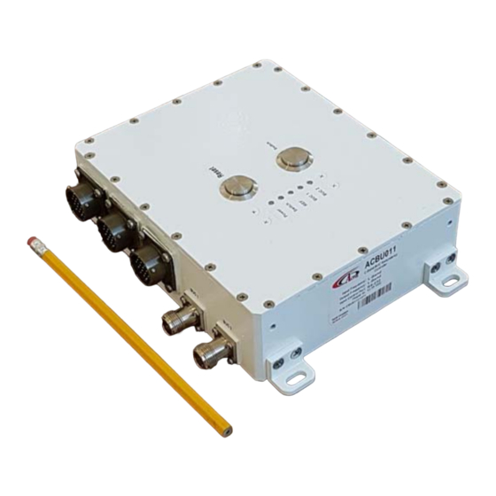
ACBU011/ACLU011 User Manual Block Overview Mechanical Drawing The appearance of the Redundancy Controller and its connectors are displayed on the below Figure 1. Figure 1 — Redundancy Controller Mechanical Drawing Page 4 of 23... -
Page 5: Technical Specifications Of Buc Redundancy Controller
ACBU011/ACLU011 User Manual Technical Specifications of BUC Redundancy Controller The technical specifications of BUC Redundancy Controller are displayed on the below figure 2. Figure 2- Technical Specifications & Connection Diagram Page 5 of 23... - Page 6 ACBU011/ACLU011 User Manual Figure 2.1- BUC Controller functional diagram Redundancy connection ports from one side: Two L-band F (or N) connectors for BUC connection provided via coaxial cable; Switch connector for connection Redundancy Controller with Switch with 19-pin cable on both sides;...
-
Page 7: Technical Specifications Of Lnb / Lna Redundancy Controller
ACBU011/ACLU011 User Manual Technical Specifications of LNB / LNA Redundancy Controller The technical specifications of the LNB/LNA Redundancy Controller are displayed on figure 3. Figure 3- Technical Specifications & Connection Diagram Page 7 of 23... - Page 8 ACBU011/ACLU011 User Manual Figure 3.1- LNB/LNA Controller functional diagram Redundancy connection ports from one side: Two L-band F (or N) connectors for BUC connection provided via coaxial cable; Switch connector for connection Redundancy Controller with Switch with 19-pin cable on both sides;...
-
Page 9: Redundancy Controller M&C Connection Instructions
ACBU011/ACLU011 User Manual III. Redundancy Controller M&C Connection Instructions Redundancy Controller 19 pin Connection for a PC / Laptop Redundancy Controller connection to PC carried by cable with 19 pin female connector (fig.4) on the one side and RJ45 (fig. 4.2), two DB9 (fig. 4.1) female connectors: RS232 and RS485 on the other side. - Page 10 ACBU011/ACLU011 User Manual Interface name Interface pin Pin Name 19-pin Connector RJ45 R75_TX R75_RX GNDISO GNDISO RS485 GNDISO GNDISO GNDISO GNDISO RS232 RS232TX RS232RX Figure 4.3 — Redundancy 19 pin connector for a PC/Laptop Page 10 of 23...
- Page 11 ACBU011/ACLU011 User Manual 19-pin Connector Pin Name 20-pin (Unit 2) 20-pin (Unit 1) Ethernet MUTE1 ALARM1 RS232_TX1 RS232_RX1 GNDISO GNDISO RS232_TX2 RS232_RX2 MUTE2 ALARM2 RX_P RX_N TX_P TX_N Figure 4.4 — Redundancy 19-pin cable to Unit 1 and Unit 2...
-
Page 12: Redundancy Controller Connection For A Waveguide Switch
ACBU011/ACLU011 User Manual Redundancy Controller Connection for a Waveguide Switch Redundancy Controller connection to waveguide switch is carried by cable with 19 pin female connector on the both sides. Waveguide Switch schema is displayed on Figure 5: Figure 5 — Switch input pins... -
Page 13: Redundancy Controller Connection Via Terminal
ACBU011/ACLU011 User Manual IV.Redundancy Controller Connection via Terminal Run Redundancy Terminal v 1.1 on your PC, when it opens you will see the start window: Figure 6 — Start window On the top of the window are situated the following menu tabs: INTERFACE –... - Page 14 ACBU011/ACLU011 User Manual Figure 6.1 — Redundancy Status Window POWER SUPPLY: Redundancy power supply provides two options: by DC power supply (U DC1 and U DC2) and by RF connector from modem (Umodem). Function displays current income voltage and power port connection. Voltage is in OK if its value is within acceptable limits and in ERROR if voltage is out of limits.
- Page 15 ACBU011/ACLU011 User Manual ALARM STATUS: Displays summary failure of BUC. ALARM STATUS is an analog signal, transmitted via M&C cable. ALARM STATUS is in OK if alarmed, and in DISABLE if unalarmed. SERIAL STATUS: Displays port connection status. SERIAL STATUS is a digital signal, transmitted via M&C cable.
- Page 16 ACBU011/ACLU011 User Manual EDIT PARAMETERS — You may edit your Redundancy parameters as needed. Push button Edit in submenu PARAMETERS to open Configuration windows (fig. 6.4 and fig 6.5). Figure 6.5 - Default configurations for LNB Figure 6.4 - Default configurations for BUC SUPPLY PARAMETERS—...
- Page 17 ACBU011/ACLU011 User Manual Minimum Power/Ampere – Set the minimum Power or Current (depend from the flag in Watt/Ampere field (see fig. 4.5)) for each BUC or LNB and must be lower than minimum power (current) value for BUC or LNB, but can’t be lower than 0.02 A.
- Page 18 ACBU011/ACLU011 User Manual Push button Login and Password (fig. 6.6) to change login settings: Figure 6.6 — Login and Password settings window You can type in the new login and password in appropriate cells, and push button Set New to send this configuration to the device, or push button Set Default to restore default login (123456) and password (123456).
- Page 19 ACBU011/ACLU011 User Manual In the latest version of the software you can change waveguide position. Open inset WS on the menu push button Set Position. You will see next window: Figure 6.8 — WS Position window Push button WS Position in the window to change waveguide position.
-
Page 20: Redundancy Controller Connection Via Ethernet
ACBU011/ACLU011 User Manual V. Redundancy Controller connection via Ethernet Connect Redundancy controller to your PC/Laptop via Ethernet, switch on the device and open the internet browser. In the address line type in IP address of your Redundancy (by default IP address: 192.168.1.249) and you will see log in window (fig. 7): Figure 7 —... - Page 21 ACBU011/ACLU011 User Manual POWER SUPPLY: Redundancy power supply provides two options: by DC power supply (U DC1 and U DC2) and by RF connector from modem (Umodem). Function displays current income voltage and power port connection. Voltage is in OK if its value is within acceptable limits, and in ERROR if voltage is out of limits or supply is not connected.
- Page 22 ACBU011/ACLU011 User Manual Push button Redundancy Parameters which is located in the bottom of the page to change the parameters of your device. You will see the next page: Supply parameters — Set the minimum/maximum parameters for voltage, power or amperage supply and waveguide switch motor voltage value: Minimum DC –...
- Page 23 ACBU011/ACLU011 User Manual Alarm Enable— Enable or disable summary BUC alarm via M&C cable. Power Enable — Enable or disable power supply alarm for BUC or LNB. Push button Set Parameters to apply changes. Login Password field - Set the new login or password and push the button Set Login &...
Need help?
Do you have a question about the ACBU011 and is the answer not in the manual?
Questions and answers