
Related Manuals for Pickering 60-890-003


Summary of Contents for Pickering 60-890-003
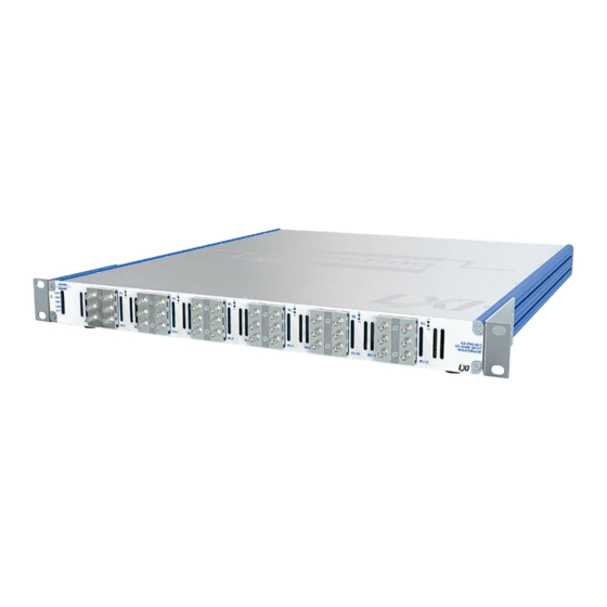
- Page 1 60-890-003 User Manual LXI 50Ω Microwave SPDT Relay pickeringtest.com Issue 1.5 March 2022...
- Page 2 © COPYRIGHT (2022) PICKERING INTERFACES. ALL RIGHTS RESERVED. No part of this publication may be reproduced, transmitted, transcribed, translated or stored in any form, or by any means without the written permission of Pickering Interfaces. Technical details contained within this publication are subject to change without notice.
- Page 3 Pickering Interfaces strives to fulfil all relevant environmental laws and regulations and reduce wastes and releases to the environment. Pickering Interfaces aims to design and operate products in a way that protects the environment and the health and safety of its employees, customers and the public. Pickering Interfaces endeavours to develop and manufacture products that can be produced, distributed, used and recycled, or disposed of, in a safe and environmentally friendly manner.
-
Page 4: Product Safety
If this product is heavy reference should be made to the safety instructions for provisions of lifting and moving. STATIC SENSITIVE To indicate that static sensitive devices are present and handling precautions should be followed. REED RELAY MODULE 40-110/115/120/125 LXI 50Ω MICROWAVE SPDT RELAY 60-890-003 Page (IV) Page (IV) -
Page 5: Table Of Contents
LXI Status Indicators ..........6.1 Troubleshooting Guide ..........6.2 LAN Reset ..............6.2 Section 7 Maintenance Information ............7.1 Microwave Multiplexer Parts List ........7.2 General Maintenance ............7.5 Microwave Relay Removal/Refitting ......7.8 Appendix A Fitting Rack Mounting Flanges ..........A.1 LXI 50Ω MICROWAVE SPDT RELAY 60-890-003 Page (V) - Page 6 THIS PAGE INTENTIONALLY BLANK LXI 50Ω MICROWAVE SPDT RELAY 60-890-003 Page (VI)
-
Page 7: Warnings And Cautions
I/O signals that may be present. Blanking panels are available to order from Pickering. If the product is not used in this manner for example by using an extender card then additional care must be taken to avoid contact with exposed signals. - Page 8 AND USERS SHOULD CONNECT TO THE FRONT PANEL CONNECTORS WITH (0.8–1.1 N·m) for stainless steel connectors. CONNECTORS OR CABLE ASSEMBLIES THAT ENSURE OPERATORS WILL NOT INADVERTENTLY COME IN CONTACT WITH HIGH VOLTAGES. LXI HIGH VOLTAGE 2-POLE MATRIX 60-310 Page viii LXI 50Ω MICROWAVE SPDT RELAY 60-890-003 Page (VIII)
- Page 9 3 Year Warranty Relay 4 NO 4 Com 4 The 60-890-003 Microwave Relay is suitable for switching 50 Ω signals NC 4 up to 18 GHz. With 12 banks of SPDT relays it is ideal for constructing Relay 5 NO 5 complex microwave switching systems for many applications.
- Page 10 <1.4:1 to 18 GHz RF Average Carry Power at 25°C: 240 W to 3 GHz 150 W to 8 GHz 120 W to 12.4 GHz 100 W to 18 GHz Typical VSWR Plot pickeringtest.com LXI 50Ω MICROWAVE SPDT RELAY 60-890-003 Page 1.2...
- Page 11 Up to 90 % non-condensing Altitude: 15000 m Safety & CE Compliance All modules are fully CE compliant and meet applicable EU directives: Low-voltage safety EN61010-1:2010, EMC Immunity EN61326-1:2013, Emissions EN55011:2009+A1:2010. pickeringtest.com LXI 50Ω MICROWAVE SPDT RELAY 60-890-003 Page 1.3...
- Page 12 91-100-101 Product Customization Pickering LXI units are designed and manufactured on our 60-750/751 LXI Microwave Matrix. Bandwidth up to own flexible manufacturing lines, giving complete product 20 GHz and is available in sizes from Single 3x3 up to control and enabling simple customization to meet very Dual 4x4 with Loop-Thru and termination options.
- Page 13 To learn more, please go to: pickeringrelay.com Programming Pickering provide kernel, IVI and VISA (NI & Keysight) drivers which are compatible with all Microsoft supported versions of Windows and popular older versions. For a list of all supporting operating systems, please see: pickeringtest.com/os The VISA driver is also compatible with Real-Time Operating Systems such as LabVIEW RT.
- Page 14 Three Year Warranty & Guaranteed Long-Term Support All standard products manufactured by Pickering Interfaces are warranted against defective materials and workmanship for a period of three years from the date of delivery to the original purchaser. Extended warranty and service agreements are available for all our modules and systems with various levels to suit your requirements.
-
Page 15: Technical Description
FUNCTIONAL DESCRIPTION The 60-890-003 is a microwave switching unit with an array of 12 SPDT relays under the control of an LXI interface designed for the routing of signals with frequencies up to 18GHz. The switches can be used in isolation or cascaded to form larger complex switching networks. - Page 16 SECTION 2 - TECHNICAL DESCRIPTION pickering THIS PAGE INTENTIONALLY BLANK LXI 50Ω MICROWAVE SPDT RELAY 60-890-003 Page 2.2...
-
Page 17: Installation
INSTALLING THE MICROWAVE SPDT RELAY The 60-890-003 may be mounted on a desk top or fitted into a standard 19 inch rack (rack mounting flanges are supplied with the unit that can be fitted to the sides of the front panel). When fitting into a rack it is important to... -
Page 18: Setting The Ip Address
Once you have the required information, the IP configuration window is used to manually set the IP address. This is shown in Figure 3-3. The current IP address setting of the 60-890-003 is indicated on an LCD display on the rear panel of the chassis. Figure 3-2. Display for IP Address on Rear Panel Incorrect setting will result in a loss of communication and may also be indicated by a red LAN LED on the front panel. -
Page 19: Installing The Software
SOFT FRONT PANEL OPERATION The 60-890-003 Microwave SPDT Relay can be programmed using the General Soft Front Panel. To access the General Soft Front Panel click the icon on the desktop. An example of this is shown in Figure 4.3. For a description of the controls, refer to “Using The Soft Front Panel”... - Page 20 SECTION 3 - INSTALLATION pickering THIS PAGE INTENTIONALLY BLANK LXI 50Ω MICROWAVE SPDT RELAY 60-890-003 Page 3.4...
-
Page 21: Programming Guide
SECTION 4 - PROGRAMMING GUIDE PROGRAMMING OPTIONS FOR PICKERING INTERFACES LXI DEVICES For information on the installation and use of drivers and the programming of Pickering’s products in various software environments, please refer to the Software User Manual. This is available as a download from: https://www.pickeringtest.com/support/software-drivers-and-downloads... -
Page 22: Programming The 60-890
PROGRAMMING THE 60-890-003 The 60-890-003 is fitted with 12 separate un-terminated SPDT microwave switches. The unit’s architecture is shown in the default, un-programmed state in Figure 4-1 below. Each switch is controlled with a separate bit in the same programming sub-unit as outlined in Table 4-1. - Page 23 Direct I/O Driver, piplx The Direct I/O driver is composed of a suite of separate libraries which interact to provide full control of a Pickering LXI unit. In the case of a switch card the communications library picmlx, and the switching library piplx, are needed.
- Page 24 Switch closures are made using the pi40iv_Connect function and released using the pi40iv_Disconnect function. The following code snippet demonstrates the minimum steps required to operate a switch on a Pickering LXI unit. First a device session is opened on the card located at bus 0, device 20 inside the LXI unit at 192.168.1.100.
- Page 25 SSH (Secure SHell) Interface Refer to the section “Command Line Control of Pickering LXI Instruments” on the following pages for details of how to open this interface and general information on the command set available. After opening an SSH session the 60-890 is controlled as follows: To select a multiplexer sub-unit on the LXI unit (card 1), type AD followed by the card number and sub-unit number eg: AD 1 2 (this will select multiplexer bank 2).
-
Page 26: Command Line Control
LXI instrument from the Windows utility PILMon and provides identical functionality. Enabling the Command Line Control Utility Pickering LXI devices do not provide an SSH server in the normal configuration state, the service must be explicitly enabled. - Page 27 LAN Reset button located at the rear of the device in the appropriate manner, refer to Section 7 of this manual for details of this process. Disabling security will stop the SSH service. LXI 50Ω MICROWAVE SPDT RELAY 60-890-003 Page 4.7...
- Page 28 First start up the SSH client and enter the IP address of the LXI device. The user will be prompted for a login name and password. The username for instrument control is ‘sshuser’, the password is that defined by the user when setting security. LXI 50Ω MICROWAVE SPDT RELAY 60-890-003 Page 4.8...
- Page 29 Before attempting to control a card it is important to understand the switch architecture of that card and to know how to address the required switch. Each Pickering switch card is represented as a set of one or more sub-units, each sub-unit containing one or more switches.
- Page 30 In the case of matrix sub-units, the XC and XO commands are useful, obviating the need for the user to calculate the bit position for a crosspoint in the matrix by allowing a point to be addressed by row and column address. LXI 50Ω MICROWAVE SPDT RELAY 60-890-003 Page 4.10...
- Page 31 = UNMASK|MASK an individual output MB <bit_pattern> = set OUTPUT sub-unit mask (to hex bit-pattern) = view sub-unit output mask (as hex bit-pattern) = take control of all Pickering switch cards = release control of all Pickering switch cards VO <bus> <slot> = open card at specified location VC <card>...
-
Page 32: Using The Soft Front Panel
When the General Soft Front Panel in opened, select the 60-890-003 from the list of LXI devices. Open the 60-890-003 device and the sub-unit within the unit is displayed using the List tab. In the case of the 60- 890-003, this is a single sub-unit LXI 50Ω... - Page 33 The sub-units can be opened by selecting the Switch tab. The bits within the sub-unit are shown as boxes each corresponding to a microwave switch. These can be selected and deselected by clicking on them. LXI 50Ω MICROWAVE SPDT RELAY 60-890-003 Page 4.13...
- Page 34 SECTION 4 - PROGRAMMING GUIDE pickering THIS PAGE INTENTIONALLY BLANK LXI 50Ω MICROWAVE SPDT RELAY 60-890-003 Page 4.14...
-
Page 35: Connections
5/16 inch wrench. This should be 3-5 in·lbs (0.3 to 0.6 N·m) for brass, and 7-10 in·lbs (0.8–1.1 N·m) for stainless steel connectors. LXI 50Ω MICROWAVE SPDT RELAY 60-890-003 Page 5.1... - Page 36 SECTION 5 - CONNECTOR INFORMATION pickering Ethernet Port LAN Reset Service Port (for Pickering diagnostics only) IP Address Display Figure 5-2. Rear Panel Layout for the 60-890-003 LXI Microwave SPDT Relay Mains Inlet Fuses Power Switch LXI 50Ω MICROWAVE SPDT RELAY 60-890-003 Page 5.2...
-
Page 37: Trouble Shooting
Refer to the Warnings and Cautions at the front of this manual INSTALLATION PROBLEMS The Plug & Play functionality of Pickering switching products generally ensures trouble-free installation. If you do experience any installation problems you should first ensure that all cables are properly connected. -
Page 38: Troubleshooting Guide
Q All of my device’s lights are on, why don’t I see a green Ready light, even after a few minutes? Your device has a fault, contact your local sales office. Please contact your local Pickering Interfaces sales office for any further support or email: Lxisupport@pickeringtest.com You can also visit our website for product updates, help and downloadable materials at: http://www.pickeringtest.com... -
Page 39: Maintenance Information
PCB. The tables can be used in the fault finding process and should be used in conjunction with the corresponding PCB layout diagrams to identify the position of faulty relays. LXI HIGH DENSITY EMR MATRIX 60-550/551 LXI 50Ω MICROWAVE SPDT RELAY 60-890-003 Page 7.1 Page 7.1... - Page 40 MICROWAVE SWITCHING UNIT PARTS LIST The 60-890-003 LXI Microwave SPDT Relay chassis contains 12 microwave relays, 2 Relay Driver PCBs as well as 2 Power Supplies and a Microcontroller assembly. The following pages provide a parts list and internal layout for the PCBs and sub-assemblies that make up the unit.
- Page 41 SECTION 7 - MAINTENANCE INFORMATION pickering Table 7-1. 60-890-003 LXI Microwave SPDT Relay Unit Chassis Parts List Pickering Part Manufacturer Description Value/Type Number Part Number Multi-Rail Power Supply “PSU1” ±12V, +5V, +3.3V C-PS-009 VLT-130-4100 Single Rail Power Supply “PSU2” +12V...
- Page 42 SPDT Relay Power Supply PSU 1 Relay 10 SPDT Relay LED Board Relay 11 SPDT Relay Relay 12 SPDT Relay LED Board Figure 7-2. 60-890-003 LXI Microwave SPDT Relay Unit Internal Components LXI 50Ω MICROWAVE SPDT RELAY 60-890-003 Page 7.4...
-
Page 43: General Maintenance
PCI bus into a serial data stream which is fed via a ribbon cable to the first relay driver board. Two relay driver boards are fitted to the 60-890-003, the second board receives its serial data from the first board in a daisy-chain configuration via a ribbon cable. - Page 44 Air passes through the processor/PSU area of the chassis and is expelled through vents in the rear panel. The fans are supplied from the Fan Controller board which is supplied with 12V directly from PSU 2. LXI 50Ω MICROWAVE SPDT RELAY 60-890-003 Page 7.6...
- Page 45 Assy. (A-PC-1257) Switch (C-CN-1195) Driver Board 2 With Fuse Drawer (A-PC-1363) LED Board (C-CN-1196) (PCB 1364) 60-890-003 CHASSIS Mains Power Input Figure 7-4. Internal Wiring for the 60-890-003 LXI Microwave SPDT Relay Unit LXI 50Ω MICROWAVE SPDT RELAY 60-890-003 Page 7.7...
-
Page 46: Microwave Relay Removal/Refitting
MICROWAVE RELAY REMOVAL/REFITTING The microwave relays of the 60-890-003 are replaceable units, in case of failure, they can easily be changed by the user. The relays are removed in pairs from the front panel without opening the chassis covers or removing the chassis from it’s rack installation. - Page 47 - in this case Relay 4. 7. With the relay disconnected, remove the two 1.5mm hexagon screws securing it to the adjacent relay. 8. The faulty relay can now be replaced. LXI 50Ω MICROWAVE SPDT RELAY 60-890-003 Page 7.9...
- Page 48 12. Secure the relay pair using the two screws removed in step 2. 13. Finally, re-connect the RF cabling, power on the chassis and test the functionality of the new relay. LXI 50Ω MICROWAVE SPDT RELAY 60-890-003 Page 7.10...
-
Page 49: Fitting Rack Mounting Flanges
APPENDIX A - FITTING RACK MOUNTING FLANGES Pickering’s LXI devices are supplied with mounting flanges to enable fitting into a standard 19 inch rack. The following procedure describes the attachment of the flanges to the unit’s side extrusions, a No.1 cross head screwdriver will be required. - Page 50 APPENDIX A - FITTING RACK MOUNTING FLANGES pickering THIS PAGE INTENTIONALLY BLANK LXI 50Ω MICROWAVE SPDT RELAY 60-890-003 Page A.2...
Need help?
Do you have a question about the 60-890-003 and is the answer not in the manual?
Questions and answers