Table of Contents
Advertisement
Quick Links
Introduction:
The SE Controls Variable Speed Fan Control Panel is a fixed modular
design that is built and tested to provide a method of operating a
single 400 V three phase 50Hz duty / standby fan arrangement.
It must not be used for any other application or in conjunction with
other manufacturers' products without prior consultation with
SE Controls.
Installation of this equipment must only be carried out by competent
and qualified persons.
This information pack must be retained for future reference by the client
and be made available for reference by persons installing, or servicing
the panel.
+44 (0)1543 443060
sales@secontrols.com
www.secontrols.com
VARIABLE SPEED FAN CONTROL
PANEL 15 kW - 22 kW
Technical information and operating instructions
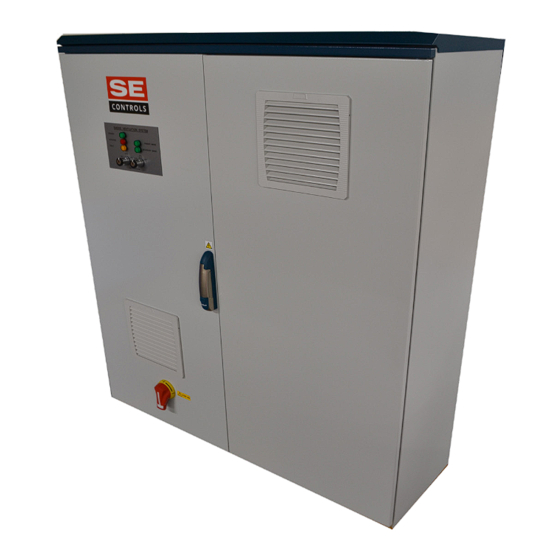
Application:
The Variable Speed Fan Control Panel is a control
system designed to operate 400 V/ 3PH/50 Hz
fans in a duty and standby configuration for
smoke control in a powered extract system.
The control of environmental fans is also possible
when specific additional packs are fitted.
Operating from a 400 Volt supply, the Variable
Speed Fan Control Panel can control fans
from 15 kW - 22 kW (Standard Versions).
Please keep these operating instructions for future reference and maintenance.
Subject to technical modifications. Diagram is not binding.
Advertisement
Table of Contents

Subscribe to Our Youtube Channel
Related Manuals for SE Controls FCS043 Series

Summary of Contents for SE Controls FCS043 Series
- Page 1 Introduction: The Variable Speed Fan Control Panel is a control The SE Controls Variable Speed Fan Control Panel is a fixed modular system designed to operate 400 V/ 3PH/50 Hz design that is built and tested to provide a method of operating a fans in a duty and standby configuration for single 400 V three phase 50Hz duty / standby fan arrangement.
-
Page 2: Table Of Contents
Contents General Information Connections, Continued 3.17. Variable Speed Fan Panel 1.1. General Safety Information Connections 1.2. Health and Safety 3.18 Activation Contacts 1.3. Environment 3.19 FOS Switch - Boost 1.4. User Responsibilities 3.20 OSLink Network 1.5. Maintenance 3.21 Outside Air Temperature Hot Corridor Solution 1.6. - Page 3 • Do NOT use this controller • Where a replacement is for any other purpose SE Controls reserves the right to needed for consumable other than that intended introduce any modifications and items e.g. fuses, they by the manufacturer.
-
Page 4: General Information
If recycling facilities are not locally available, contact SE Controls who can arrange for recycling carried out according to these instructions and to the operating instructions of the drives. -
Page 5: Maintenance
Within the UK a suitable service contract with SE Controls is recommended for this purpose. 1.8. Contact Information The system must be protected For sales, technical support and... -
Page 6: Specification
Specification 2.1. Device Overview Part number 15-22 kW Fan Control Panel FCS043XXXX Dimensions 1400 x 1200 x 400mm (H x W x D) – Standard Versions Mass Approx. 140 - 210kg Dependant on options fitted Supply 400 Vac 50/60 Hz Output Up to 27.0 A : 15 kW Version Up to 32.2 A: 18.5 kW Version... -
Page 7: Fuses
2.3. Fuses Fuse Rating Function T 3 A Service Socket Without Pressure Sensors With Pressure Sensors Main PLC (K20) Main PLC (K20) T 1 A 230 Vac Fan Damper (If Fitted) T 1 A 230 Vac NV Radial Dampers (If Fitted) X38/F01 T 1 A ATS (If Fitted) -
Page 8: Recommended Cable Types
2.5. Recommended Cables Types Cabling For Minimum number of cores Recommended Cable Type Incoming Supply 4 + Earth FP 600 or equivalent Incoming Earth Cable 10 mm² minimum or equivalent to live cores when the live cores are thicker than 10 mm²... -
Page 9: Connections
Connections 3.1. Connections The 16 mm terminals (fan connections) have a cable capacity of 4-35 mm stranded or solid. All 4 mm terminals have a cable capacity of 2.5 mm stranded or 4 mm solid. Each terminal is identified with a unique reference. Please check the circuit diagram for details. The following sections are to be used for guidance only and are subject to change. -
Page 10: Duty Fan And Stand By Fan
CONTROL PANEL DIN RAIL CONNECTIONS CONTROL PANEL DIN RAIL CONNECTIONS S:\Technical Support Team\supper hidden new logo\SED_3036_SE Controls Colour Logo 2018 TIFF.tif 3.3. Duty Fan and Standby Fan Connections (X25 & X26) S:\Technical Support Team\supper hidden new logo\SED_3036_SE Controls Colour Logo 2018 TIFF.tif INSIDE CONTROL PANEL INSIDE CONTROL PANEL DIN RAIL CONNECTIONS - X25... -
Page 11: 230 Vac Fan Connection
X27(230v) CONTROL PANEL DIN RAIL CONNECTIONS cal Support Team\supper hidden new logo\SED_3036_SE Controls Colour Logo 2018 TIFF.tif S:\Technical Support Team\supper hidden new logo\SED_3036_SE Controls Colour Logo 2018 TIFF.tif 3.5. 230 Vac NV Fan Connections (X27, if this option pack is fitted) NTROL PANEL DIN RAIL CONNECTIONS - X27 INSIDE CONTROL PANEL... -
Page 12: System Healthy Vfc
CONTROL PANEL DIN RAIL CONNECTIONS S:\Technical Support Team\supper hidden new logo\SED_3036_SE Controls Colour Logo 2018 TIFF.tif 3.7. System Healthy (VFC) (X29) DIN RAIL CONNECTIONS - X29 INSIDE CONTROL PANEL SYSTEM HEALTHY VFC IN THE FIELD CONTROL PANEL DIN RAIL CONNECTIONS S:\Technical Support Team\supper hidden new logo\SED_3036_SE Controls Colour Logo 2018 TIFF.tif 3.8. -
Page 13: 230 Vac Smoke Damper
CONTROL PANEL DIN RAIL CONNECTIONS 3.9. 230 Vac Smoke Damper (X31) S:\Technical Support Team\supper hidden new logo\SED_3036_SE Controls Colour Logo 2018 TIFF.tif DIN RAIL CONNECTIONS - X31 INSIDE CONTROL PANEL POWER CLOSE/SPRING OPEN 230 Vac SMOKE DAMPER IN THE FIELD CONTROL PANEL DIN RAIL CONNECTIONS 3.10. -
Page 14: Environmental Radial Damper
CONTROL PANEL DIN RAIL CONNECTIONS 3.11. Environmental Radial Damper (X33, if this option pack is fitted) S:\Technical Support Team\supper hidden new logo\SED_3036_SE Controls Colour Logo 2018 TIFF.tif 1.10 DIN RAIL CONNECTIONS - X33 INSIDE CONTROL PANEL IN THE FIELD RADIAL DAMPERS CONTROL PANEL DIN RAIL CONNECTIONS S:\Technical Support Team\supper hidden new logo\SED_3036_SE Controls Colour Logo 2018 TIFF.tif 3.12. -
Page 15: Generator Status
CONTROL PANEL DIN RAIL CONNECTIONS 3.13. Generator Status (X38) S:\Technical Support Team\supper hidden new logo\SED_3036_SE Controls Colour Logo 2018 TIFF.tif 1.12 DIN RAIL CONNECTIONS - X38 INSIDE CONTROL PANEL GENERATOR STATUS IN THE FIELD CLOSED CONTACT OPENS ON FAULT GENERATOR CONTROL PANEL DIN RAIL CONNECTIONS S:\Technical Support Team\supper hidden new logo\SED_3036_SE Controls Colour Logo 2018 TIFF.tif 3.14. -
Page 16: Vdc Smoke Dampers
PUSH-PULL PANEL LINK CONNECTIONS 3.15. 24 Vdc Smoke Dampers 1 (X40) S:\Technical Support Team\supper hidden new logo\SED_3036_SE Controls Colour Logo 2018 TIFF.tif 1.14 DIN RAIL CONNECTIONS X40 INSIDE CONTROL PANEL 24 Vdc SMOKE DAMPERS IN THE FIELD SMOKE DAMPER 1 PUSH-PULL PANEL LINK CONNECTIONS 3.16. -
Page 17: Variable Speed Fan Panel
PUSH-PULL PANEL LINK CONNECTIONS 3.17. Variable Speed Fan Panel Connections (X42) S:\Technical Support Team\supper hidden new logo\SED_3036_SE Controls Colour Logo 2018 TIFF.tif 1.16 DIN RAIL CONNECTIONS X42 LOCAL REMOTE DIN RAIL CONNECTIONS X42 Up to 4 panels PANEL 2 PANEL 3 DRAWING TITLE: VARIABLE SPEED PANEL CONNECTIONS S:\Technical Support Team\supper hidden new logo\SED_3036_SE Controls Colour Logo 2018 TIFF.tif... -
Page 18: Activation Contacts
CONTROL PANEL DIN RAIL CONNECTIONS CONTROL PANEL DIN RAIL CONNECTIONS CONTROL PANEL DIN RAIL CONNECTIONS CONTROL PANEL DIN RAIL CONNECTIONS 3.19. Activation Contacts (X43,X44, X45, X46) S:\Technical Support Team\supper hidden new logo\SED_3036_SE Controls Colour Logo 2018 TIFF.tif S:\Technical Support Team\supper hidden new logo\SED_3036_SE Controls Colour Logo 2018 TIFF.tif S:\Technical Support Team\supper hidden new logo\SED_3036_SE Controls Colour Logo 2018 TIFF.tif S:\Technical Support Team\supper hidden new logo\SED_3036_SE Controls Colour Logo 2018 TIFF.tif 1.17... -
Page 19: Fos Switch - Boost
CONTROL PANEL DIN RAIL CONNECTIONS 3.19. FOS Switch - Boost (X47) S:\Technical Support Team\supper hidden new logo\SED_3036_SE Controls Colour Logo 2018 TIFF.tif 1.21 DIN RAIL CONNECTIONS INSIDE CONTROL PANEL FOS SWITCH - BOOST IN THE FIELD FIREMANS OVERRIDE BOOST SWITCH SWITCH CONTROL PANEL DIN RAIL CONNECTIONS S:\Technical Support Team\supper hidden new logo\SED_3036_SE Controls Colour Logo 2018 TIFF.tif... -
Page 20: Outside Air Temperature Hot Corridor Solution
CONTROL PANEL DIN RAIL CONNECTIONS 3.21. Outside Air Temperature Sensor Hot Corridor Solution (X49) S:\Technical Support Team\supper hidden new logo\SED_3036_SE Controls Colour Logo 2018 TIFF.tif 1.23 DIN RAIL CONNECTIONS - X49 INSIDE CONTROL PANEL OUTSIDE AIR TEMPERATURE SENSOR IN THE FIELD HOT CORRIDOR SOLUTION TASC BOARD... -
Page 21: Test Switch
CONTROL PANEL DIN RAIL CONNECTIONS S:\Technical Support Team\supper hidden new logo\SED_3036_SE Controls Colour Logo 2018 TIFF.tif 3.23. Test Switch (X51) 1.25 DIN RAIL CONNECTIONS - X51 INSIDE CONTROL PANEL TEST SWITCH IN THE FIELD TEST SWITCH PUSH-PULL PANEL LINK CONNECTIONS S:\Technical Support Team\supper hidden new logo\SED_3036_SE Controls Colour Logo 2018 TIFF.tif 3.24. -
Page 22: System Design
This is beyond the scope of this document. If in doubt, consult SE Controls or approved agents who can give further guidance. The system design documentation should include the ‘Cause and Effect’ list or similar to identify the essential smoke control functions of the system. -
Page 23: Installation, Commissioning And Fault Finding
Installation, Commissioning and Fault Finding 5.1. Fixing When installing a panel internally, the fixing brackets should be screwed to the panel first. Then, hold the panel against the surface to which it is to be fixed. Mark through the holes. Drill appropriately sized pilot/fixing holes and use plastic plugs/cavity fixings where appropriate. -
Page 24: First Power Up Tests
5.2. First power-up tests Full commissioning of a new system requires the availability of three phase and neutral electrical supply. If activation is via a fire alarm controlled relay, ensure the fire alarm is normally closed when the system is healthy. For networked systems, an unbound, faulty or disconnected OSlink card may cause a fault indication. -
Page 25: Inverter First Time Set Up And Parameters
5.3. Inverter First Time Set Up and Parameters Below is a list of parameters that will be set during the production build and test. These parameters are valid for the ACH580 range and Standard Versions only. Parameter Setting Required Description 20.01 Embedded Fieldbus Ext1 Commands... -
Page 26: Basic Fault Finding For Standard Version
5.4. Basic Fault Finding for Standard Version No operation, No LEDs illuminated. Check if the isolator S01 is switched on. Check if all circuit breakers are toggled to the ON position. Measure the voltage between the terminal “a” (top) of X17 and terminal “a” (top) of X18, which should be 24 Vdc +/- 5 Vdc. -
Page 27: Circuit Diagram
Circuit Diagram 6.1. Variable Speed Fan Control Panel 15kW-22kW Please keep these operating instructions for future reference and maintenance. +44 (0)1543 443060 Subject to technical modifications. Diagram is not binding. sales@secontrols.com For a larger version of this diagram, please contact: technicalsupportteam@secontrols.com www.secontrols.com... - Page 28 Notes: Please keep these operating instructions for future reference and maintenance. +44 (0)1543 443060 Subject to technical modifications. Diagram is not binding. sales@secontrols.com For a larger version of this diagram, please contact: technicalsupportteam@secontrols.com www.secontrols.com...
- Page 29 Fradley Park, Lichfield www.secontrols.com Staffordshire WS13 8RZ United Kingdon Name & registered office: Loanguard Limited, Lancaster House, Wellington Crescent, Fradley Park, Lichfield, Staffordshire WS13 8RZ United Kingdom Company No.01468061 Vat No.377 5600 30 - SE Controls is a Registered Trademark...
Need help?
Do you have a question about the FCS043 Series and is the answer not in the manual?
Questions and answers