Table of Contents
Advertisement
Available languages
Available languages
Quick Links
Prima di iniziare ad operare con
la macchina, leggere attenta-
mente le istruzioni per l'uso.
Before starting to work with the
machine, operation read the
instructions for use.
PROW 18
IT Istruzioni per l'uso e manutenzione
SALDATRICI/ALTERNATORI
Istruzioni originali
L'INSTALLAZIONE DEVE ESSERE EFFETTUATA SOLO DA PER-
SONALE AUTORIZZATO DALLA LINZ ELECTRIC SPA
EN Operating and Maintenance manual
WELDERS/ALTERNATORS
With translation of the original instructions
THE INSTALLATION MUST BE PERFORMED ONLY BY PERSON-
NEL AUTHORIZED BY LINZ ELECTRIC SPA
Ed: 1/2023
Advertisement
Table of Contents
Troubleshooting

Related Manuals for Linz PROW 18


Summary of Contents for Linz PROW 18
- Page 1 IT Istruzioni per l’uso e manutenzione SALDATRICI/ALTERNATORI Istruzioni originali L’INSTALLAZIONE DEVE ESSERE EFFETTUATA SOLO DA PER- SONALE AUTORIZZATO DALLA LINZ ELECTRIC SPA EN Operating and Maintenance manual WELDERS/ALTERNATORS With translation of the original instructions THE INSTALLATION MUST BE PERFORMED ONLY BY PERSON-...
-
Page 2: Table Of Contents
MOVIMENTAZIONE ALTERNATORI ALTERNATORS HANDLING PERICOLO DANGER A) SCOTTATURE A) BURNS B) SHOCK ELETTRICO B) ELECTRIC SHOCK C) ATTENZIONE ALLE MANI C) BEWARE TO HANDS INDICE INDEX 1. Misure di sicurezza ............1. Safety instruction ............16 2. Descrizione dell’alternatore ........2. -
Page 3: Misure Di Sicurezza
ITALIANO PROW 18 SALDATRICI DC / ALTERNATORI TRIFASE 4 POLI, SENZA SPAZZOLE CON ECCITATRICE 1. MISURE DI SICUREZZA Prima di utilizzare il gruppo elettrogeno è indispensabile leggere il manuale “Uso e manutenzione” del gruppo elettro- geno e dell’alternatore e seguire le raccomandazioni seguenti. -
Page 4: Messa In Servizio
ITALIANO 3. MESSA IN SERVIZIO Le seguenti operazioni di controllo e di messa in servizio devono essere eseguite solo da personale qualificato. ⇒ L’alternatore dovrà essere installato in un locale con possibilità di scambio dell’aria con l’atmosfera per impedire che la temperatura ambiente superi i valori previsti dalle norme. - Page 5 ITALIANO Fig. 1c 3) Montare i tasselli elastici del giunto. 4) Accoppiare l’alternatore al motore primo fissando con le apposite viti la campana di accoppiamento (vedi figura 1d). ATTENZIONE: per allineare i due semi-giunti, ruotare il volano e non fare leva sulla ventola dell’alternatore perché po- trebbe rompersi.
- Page 6 ITALIANO Fig. 2c 5) Centrare e fissare con le apposite viti il giunto del rotore al volano del motore primo, agendo attraverso le aperture apposite, come indicato in figura 2d. ATTENZIONE: per allineare i fori del giunto del rotore ai fori del volano, ruotare il volano e non fare leva sulla ventola dell’alternatore perché...
-
Page 7: Note Generali
6307-2RS-C3 Ponti a diodi Normalmente vengono usati dei ponti a diodi previsti per: PROW 18 5A - 1 00V Verifica dei ponti a diodi La verifica dei singoli diodi componenti il ponte di raddrizzamento può essere eseguita sia con un ohmetro che con una batteria e relativa lampada come qui di seguito descritto. -
Page 8: Regolatore Di Tensione
ITALIANO Come si vede dallo schema precedente, tutta la parte generatore della serie PROW18 viene governata dal regolatore HVR- 11, che agisce sullo statore eccitatrice della stessa. Le uscite trifase e monofase dell’alternatore, sono disponibili, opportunamente protette da interruttore magnetotermico/differenziale, nelle apposite prese. 6. -
Page 9: Funzionamento Come Saldatrice
Se si verifica quanto descritto precedentemente, il regolatore funziona correttamente. Fig. 3 - PROW 18 8. FUNZIONAMENTO COME SALDATRICE Come si vede dallo schema, la serie PROW18 è costituita da una saldatrice DC con raddrizzatore trifase a tiristori. La macchina funziona come una sorgente di corrente costante, il cui valore si può... - Page 10 ITALIANO - 10 -...
- Page 11 ITALIANO 100% Welder Enable PROW 400 100% Welder Enable PROW 500 lettrodo sul pezzo a saldare, e la stessa si porterà alla sua tensione nominale di innesco (70Vdc÷75Vdc), accendendo il led (6) di abilitazione alla saldatura. In queste condizioni, con i cavi di saldatura collegati ai terminali (5), e con la polarità appropriata, si predispone il potenziometro (1) ad un livello di corrente pari a quella indicata nella scatola di elettrodi che si desidera fondere.
-
Page 12: Norme Di Sicurezza Per La Saldatura
ITALIANO tore, induttanza), le apposite capsule termiche possono intervenire, accendendo il led (7) e diseccitando la saldatrice. Il ripristino avviene automaticamente, dopo che la capsula termica intervenuta ritorna alla temperatura di funzionamento nor- male. È possibile selezionare la corrente di saldatura tramite un potenziometro remoto, per fare ciò, si collega la scatola del poten- ziometro remoto esterno all’apposito connettore “Remote Potentiometer”... -
Page 13: Resistenze E Dati Di Eccitazione
ITALIANO Corrente di Saldatura (A) Diametro α elettrodo max. (mm) ÷ ÷ ÷ ÷ ÷ ÷ ÷ > 350 Procedimento Con la maschera davanti al viso, per innescare l’arco, strofinare la punta dell’elettrodo sul pezzo a saldare, eseguendo un movi- mento come si dovesse accendere un fiammifero. -
Page 14: Risoluzione Dei Problemi (Parte Generatore)
ITALIANO 13. RISOLUZIONE DEI PROBLEMI (PARTE GENERATORE) GUASTO CAUSE INTERVENTI 1) Insufficiente tensione residua 1) Eccitare lo statore dell’eccitatrice utilizzando una batteria 2) Interruzione di un collegamento 2) Ripristinare il collegamento 3) Ponte a diodi rotante guasto 3) Sostituire il ponte a diodi rotante L’alternatore non si eccita 4) Velocità... -
Page 15: Risoluzione Dei Problemi (Parte Saldatrice)
ITALIANO 14. RISOLUZIONE DEI PROBLEMI (PARTE SALDATRICE) GUASTO CAUSE INTERVENTI 1) Intervento auto-limitazione di sicurezza 1) Strisciare l’elettrodo sul pezzo a saldare 2) Intervento di alcuna capsula termica 2) Attendere ripristino capsula/led 3) Circuito di controllo CS-18 guasto 3) Sostituire circuito di controllo CS-18 4) Contato incerto di alcun connettore del circuito 4) Controllare e ripristinare il corretto inserimento dei connettori CS-18... -
Page 16: Safety Instruction
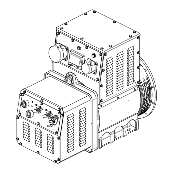
DANGER! Refers to an immediate risk that may cause serious personal injury or death. 2. ALTERNATOR DESCRIPTION The PROW 18 series is comprised of DC welders/three-phase 4 poles brushless alternators with exciter and electronic regula- tor. These machines permit simultaneous welding and load feeding. The welder function is controlled by an electronic system that maintains a constant welding current. -
Page 17: Installation And Start Up
ENGLISH 3. INSTALLATION AND START UP Only qualified personnel should carry out the following start up and control operations. The alternator must be installed in a well ventilated room. The ambient temperature should not exceed standard ⇒ recom-mended values. It is important to ensure that the air inlets and outlets are never obstructed. When installing the alternator it is impor-tant ⇒... - Page 18 ENGLISH Mount the coupling’s rubber blocks Couple the alternator to the drive motor by securing, with suitable screws, the adaptor to the motor (see figure 1d). WARNING: to align the two half-couplings, turn the engine’s flywheel and do not turn the alternator’s fan since it could break.
- Page 19 ENGLISH Centre and secure the coupling disc to the drive motor’s flywheel using appropriate screws, working through the air outlets as indicated in figure 2d. WARNING: to align the rotor coupling disc holes to the flywheel holes, turn the engine’s flywheel and do not turn the alternator’s fan since it could break.
-
Page 20: General Notes
Diode bridge The following diodes are normally used: PROW 18 5A - 1 00V Checkout of the diode bridge The checkout of the individual diode valves of a rectifier bridge can be executed using either an ohmmeter or a battery and relative lamp as described below. -
Page 21: Voltage Regulation
ENGLISH MAIN ROTOR ROTATING BRIDGE EXCITER ELECTRONIC REGULATOR HVR-11 VG: VOLTAGE TRIMMER. It increases in clockwise direction ST: STABILITY TRIMMER. It increases in clockwise direction Hz: UNDER FREQUENCY TRIMMER. The protection is off in clockwise direction OL: OVER LOAD TRIMMER. The protection is OFF in clockwise direction GENERATOR MAIN WINDING STATOR 230V/400V 50Hz... -
Page 22: Operation As Welder
The stability control acts on the dynamic response of the system thus ensuring that the creation of oscillations in the outlet voltage value is avoided. The regulator is preset by Linz Electric S.r.l. in order to obtain the best performance in the vast majority of applications. - Page 23 ENGLISH - 23 -...
-
Page 24: Safety Instructions For Welding
ENGLISH 100% Welder Enable PROW 400 100% Welder Enable PROW 500 9. SAFETY INSTRUCTIONS FOR WELDING - Avoid any direct contact with the welding circuit, the arc striking tension of the welding outlet can be dangerous in some circumstances. - Effect checkout and repairing operations of the system only when the generator is completely stopped. - Accomplish equipotential connection of all metallic parts according to national safety rules, as well as for any eventual con- nection to earth. -
Page 25: Installation
ENGLISH - Remove all flammable materials like wood, paper, rags, etc. from the working area. - Provide adequate ventilation or facilities for the removal of welding fumes near the arc. - Always protect your eyes with appropriate inactinic glasses mounted on a welding mask or helmet. Use proper gloves and protective clothing in order to avoid the exposure of your skin to the welding arc. -
Page 26: Resistances And Excitation Data
ENGLISH 12. RESISTANCES AND EXCITATION DATA EXCITER EXCITATION WINDING RESISTANCES (Ω ) @ 20°C DATA GENERATOR EXCITER NO LOAD WELDER GENERATOR TYPE ROTOR STATOR STATOR Stator Rotor Vexc.(Vdc) Iexc.(Adc) PROW18 400 dc 0.83 0.0135 13.15 0.91 PROW18 500 dc 0.64 0.0078 13.15 0.84... -
Page 27: Trouble Shooting (Welder)
ENGLISH FAULT CAUSE SOLUTION 1) Intervention of safe self-limiting function 1) Strike the electrode tip on the work piece 2) Intervention of a thermal protection 2) Wait for the automatic reset of thermal protection 3) CS18 welder controller broken 3) Replace CS18 welder controller 4) Uncertain contact in a CS18 connector 4) Check and correct the connector contact Low start voltage... -
Page 28: Parti Di Ricambio
RICAMBI - SPARE PARTS - PROW 18 - 28 -... - Page 29 N° RICAMBI SPARE PARTS CARCASSA CON STATORE FRAME WITH STATOR INDUTTORE ROTANTE B14 B14 ROTATING INDUCTOR INDUTTORE ROTANTE MD35 MD35 ROTATING INDUCTOR SCUDO POSTERIORE N.D.E. BRACKET SCUDO ANTERIORE B3/B14 B3/B14 D.E. COVER SCUDO ANTERIORE SAE5 SAE5 D.E. ADAPTER SCUDO ANTERIORE SAE4 SAE4 D.E.
-
Page 30: Dichiarazione Di Conformità E Di Incorporazione
DECLARATION OF CONFORMITY E DI INCORPORAZIONE AND INCORPORATION Il costruttore LINZ ELECTRIC Spa - Viale del Lavoro, The manufacturer LINZ ELECTRIC Spa - Viale del Lav- 30 - 37040 Arcole (Vr) Italia, dichiara che i componenti oro, 30 - 37040 Arcole (VR) Italy, declares that the com-... - Page 31 - 31 -...
- Page 32 LINZ ELECTRIC Spa Società a Socio Unico Viale del Lavoro, 30 - 37040 Arcole (Vr) Italia Tel. +39 045 7639201 - Fax +39 045 7639202 www.linzelectric.com - info@linzelectric.com...
Need help?
Do you have a question about the PROW 18 and is the answer not in the manual?
Questions and answers