
Related Manuals for GENYX ENERGY GPRO2200-1


Summary of Contents for GENYX ENERGY GPRO2200-1
- Page 1 ORIGINAL INSTRUCTION > EN Gasoline Generator Instruction Manual Model: GPRO2200-1 BUILDER 32, rue Aristide Bergès - ZI 31270 Cugnaux - France Warning: Please read the manual carefully before using the unit!
-
Page 2: Table Of Contents
CONTENTS 1. SAFETY INSTRUCTION 2. COMPONENT IDENTIFICATION 3. CONTROLS 1) Engine Switch 2) Recoil Starter 3) Fuel Valve 4) Choke 5) Circuit Breaker 6) Ground Terminal 7) Oil Alert System 4. GENERATOR USE 1) Connections to a Building's Electrical System 2) Ground System 3) AC Applications 4) AC Operation... -
Page 3: Safety Instruction
1. SAFETY INSTRUCTION Warning: 1. Attention! Exhaust gases are toxic. Do not operate the generator in a room without ventilation system! 2. Children should be protected by keeping them at a safe distance from the generator set! 3. Refilling of the generating sets are not allowed during the operation! 4. - Page 4 Run the generator in respect of the power indicated in the user’s manual. Do not run the generator with an overload or at excessive speed. The silencer of the generator becomes extremely hot when the motor runs or even for a time after it has stopped.
- Page 5 Engine exhaust gases are toxic. Do not operate the generating set in unventilated rooms. When installed in ventilated rooms, additional requirements for fire and explosion protection shall be observed. Before use, the generating set and its electrical equipment (including lines and plug connections) should be checked to ensure that they are not defective.
- Page 6 Carry out filling in a safe place, and slowly open the fuel cap to release the pressure which has built up inside the tank. Wipe up any drops of petrol that have spilled before starting the motor. To prevent fire, move the generator at least 4 metres away from the area for filling with fuel. ...
- Page 7 Before connecting electrical devices to the generator, make sure that their voltage specifications and frequency of functioning correspond to the technical characteristics of the generator. There may be damage if the device connected is not designed to function with a voltage tolerance of +/- 10% or a frequency tolerance of +/- 3 % compared with those of the generator.
-
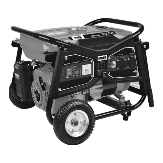
Page 8: Component Identification
Electrical hazard Carbon monoxide (CO)danger Fire hazard Risk of being burnt 2. COMPONENT IDENTIFICATION NOTE: Diagrams may vary according to the types. - Page 9 INSTALLATION 1) Wheels Put upside down the tool. Add the axis on the support On each side add a washer, a wheel, a washer and a pin to lock the wheel in place. 2) Foot pad Keep the tool upside down. In the food pad (2 pieces), put a washer and a screw on each foot pad Localise the two holes on the bar.
-
Page 10: Controls
3. CONTROLS 1) Engine Switch To start and stop the engine. Switch position: OFF: To Stop the engine. Key can be removed/inserted. ON: To run the engine after starting. START: To start the engine by turning the starter motor. With in Electric Starter Without Electric Starter Return the key to the ON position once the engine has started. - Page 11 4) Choke The choke is used to provide an enriched fuel mixture when starting a cold engine. It can be opened and closed by operating the choke lever or choke rod manually. Move the lever or the rod to the CLOSE position to enrich the mixture. 5) Circuit Breaker The circuit breaker will automatically switch OFF if there is a short circuit or a significant overload of the generator at the receptacle.
-
Page 12: Generator Use
7) Oil Alert System The oil alert system is designed to prevent engine damage caused by an insufficient amount of oil in the crankcase. Before the oil level in the crankcase can fall below a safe limit, the oil alert system will automatically shut down the engine (the engine switch will remain in the ON position). - Page 13 Special Requirements There may be Federal or State Occupational Safety and Health Administration (OSHA) regulations, local codes, or ordinances that apply to the intended use of the generator. Please consult a qualified electrician, electrical inspector, or the local agency having jurisdiction. •...
- Page 14 ②Switch the AC circuit breaker ON. ③ Plug in the appliance. Most motorized appliances require more than their rated wattage for startup. Do not exceed the current limit specified for any one receptacle. If an overloaded circuit causes the AC circuit breaker to switch OFF, reduce the electrical load on the circuit, wait a few minutes and then reset the circuit breaker.
- Page 15 4) Connect the negative (-) battery cable to the battery negative (-) terminal. 5) Connect the other end of the negative (-) battery cable to the generator. 6) Start the generator. NOTICE Do not start the vehicle while the battery charging cables are connected and the generator is running.
-
Page 16: Pre-Operation Check
Even with suitable carburetor jetting, engine horsepower will decrease approximately 3.5% for each 1000 foot (300 meter) increase in altitude. The effect of altitude on horsepower will be greater than this if no carburetor modification is made. NOTICE If a engine jetted for high altitude is used at a lower altitude, the lean air fuel mixture will reduce performance and may over-heat and seriously damage the engine. - Page 17 2) Fuel Recommendation 1. Check the fuel level gauge. 2. Refill the tank if the fuel level is low. Do not fill above the shoulder of the fuel strainer. WARNING • Gasoline is extremely flammable and is explosive under certain conditions. •...
- Page 18 NOTICE Running the engine with persistent spark knock or pinging can cause engine damage. Running the engine with persistent spark knock or pinging is misuse, and the Distributor's Limited Warranty does not cover parts damaged by misuse. Oxygenated Fuels Some gasoline are blended with alcohol or an ether compound to increase the octane. These gasoline are collectively referred to as oxygenated fuels.
-
Page 19: Starting/Stopping The Engine
6. STARTING/STOPPING THE ENGINE Starting the engine 1. Make sure that the AC circuit breaker is in the OFF position. The generator may be hard to start if a load is connected. 2. Turn the fuel valve to the ON position. 3. -
Page 20: Maintenance
7. MAINTENANCE Good maintenance is essential for safe, economical, and trouble-free operation. It will also help reduce air pollution. WARNING Exhaust gas contains poisonous carbon modoxide. Shut off the engine before performing any maintenance. If the engine must be run, make sure the area is well ventilated. Periodic maintenance and adjustment is necessary to keep the generator in good operating condition. - Page 21 2) Tool kit The tools supplied with the generator will help you to perform the owner maintenance procedures listed on the following page. Always keep this tool kit with the generator. NOTE: Diagrams may vary according to the types. 3) Engine oil change Drain the oil while the engine is warm to assure complete and rapid draining 1.
- Page 22 A dirty air cleaner will restrict air flow to the carburetor. To prevent carburetor malfunction, service the air cleaner regularly. Service more frequently when operating the generator in extremely dusty areas. WARNING Using gasoline or flammable solvent to clean the filter element can cause a fire or explosion.
- Page 23 5) Fuel Sediment Cup Cleaning The sediment cup prevents dirt or water which may be in the fuel tank from entering the carburetor. If the engine has not been run for a long time, the sediment cup should be cleaned. 1) Turn the fuel valve to the OFF position.
-
Page 24: Transporting And Storage
4) Visually inspect the spark plug. Discard it if the insulator is cracked or chipped. Clean the spark plug with a wire brush if it is to be reused. 5) Measure the plug gap with a feeler gauge. Correct as necessary by carefully bending the side electrode. - Page 25 Before storing the unit for an extended period: • Be sure the storage area is free of excessive humidity and dust. • Service according to the table below: STORAGE TIME RECOMMENDED SERVICE PROCEDURE TO PREVENT HARD STARTING Less than 1 month No preparation required.
-
Page 26: Troubleshooting
4) Slowly pull the starter grip until resistance is felt. At this point, the piston is coming up on its compression stroke and both the intake and exhaust valves are closed Storing the engine in this position will help to protect it from internal corrosion. Align the notch on the starter pulley with the hole at the top of recoil starter. - Page 27 Is the fuel reaching Clean the fuel sediment cup the carburetor To check: Turn off the engine switch and lossen the drain screw. If the engine still does Fuel should flow from the not start, take the drain when the engine switch generator to an is turned on.
- Page 28 10. CIRCUIT DIAGRAM...
-
Page 29: Specifications
11. SPECIFICATIONS Engine Engine model PT170F1 Engine type Single cylinder, 4-strokes, Forced air cooling, OHV. Displacement( CC) 212cc Rated speed 3000/min Igniting system Transistor magneto Starting system Recoil Fuel Volume (L) 15 L Continuous operation time (h) 12 h Min. Fuel consumption (g/kW.h) 360 g/kW.h Lube. -
Page 30: Ec Declaration Of Conformity
12. EC DECLARATION OF CONFORMITY Declaration of conformity BUILDER SAS ZI, 32 RUE ARISTIDE BERGES – 312070 CUGNAUX – FRANCE Declares that the machinery designated below: 2000W Gasoline Generator GPRO2200- 1 Model: Serial number: 20210663402-20210663626 Complies with the provisions of the Directive “machinery” 2006/42/CE and national laws transposing it: Also complies with the following European directives: EMC Directive 2014/30/EU Rohs Directive (EU)2015/863 amending 2011/65/EU... -
Page 31: Warranty
13. WARRANTY WARRANTY The manufacturer guarantees the product against defects in material and workmanship for a period of 2 years from the date of the original purchase. The warranty only applies if the product is for household use. The warranty does not cover breakdowns due to normal wear and tear. The manufacturer agrees to replace parts identified as defective by the designated distributor. -
Page 32: Product Failure
14. PRODUCT FAILURE WHAT TO DO IF MY MACHINE BREAKS DOWN? If you bought your product in a store: a) Empty the fuel tank. b) Make sure that your machine is complete with all accessories supplied, and clean! If this is not the case, the repairer will refuse the machine. -
Page 33: Warranty Exclusions
15. WARRANTY EXCLUSIONS THE WARRANTY DOES NOT COVER: • Start-up and setting up of the product. • Damage resulting from normal wear and tear of the product. • Damage resulting from improper use of the product. • Damage resulting from assembly or start-up not in accordance with the user manual. •...
Need help?
Do you have a question about the GPRO2200-1 and is the answer not in the manual?
Questions and answers