Table of Contents
Advertisement
Quick Links
Advertisement
Table of Contents

Subscribe to Our Youtube Channel
Related Manuals for Wachendorff ZTA9648O


Summary of Contents for Wachendorff ZTA9648O
- Page 1 ZTA9648O Counter/Rate Meter User manual...
-
Page 3: Table Of Contents
Table of contents Safety guidelines ......................5 Organization of safety notices ..............5 Safety Precautions ....................6 Precautions for safe use ...................6 Environmental policy and waste disposal/ WEEE ........7 Model identification .......................8 Technical data ........................8 General data .......................8 Hardware data ....................9 Software data ....................10 Configuration mode .................. - Page 4 10.2 Loading default values ..................31 10.3 Reading and configuration through NFC ..........32 10.4 Configuration through memory card ............33 10.4.a Creation memory card ............... 33 10.4.b Loading configuration from memory card ......34 Table of configuration parameters ................34 11.1 Display ......................
-
Page 5: Safety Guidelines
Disregarding these safety guidelines and notices can be Danger! life-threatening. Disregarding these safety guidelines and notices can result Warning! in severe injury or substantial damage to property. Information! This information is important for preventing errors. User manual - ZTA9648O - 5... -
Page 6: Safety Precautions
Do not wire the terminals that are not used. • To avoid inductive noise, keep the controller wiring away from power cables that carry high voltages or large currents. Also, do not wire powerlines 6 - ZTA9648O - User manual... -
Page 7: Environmental Policy And Waste Disposal/ Weee
According to European Directive 2012/19/EU on waste electrical and electronic equipment and its implementation in accordance with national law, electric tools that have reached end of life must be collected separately and returned to an environmentally compatible recycling facility. User manual - ZTA9648O - 7... -
Page 8: Model Identification
Temperature 0-40 °C - Humidity 35..95 uR% temperature Max. altitude: 2000m IP54 (front panel) (su frontale) with gasket Sealing IP20 (box and terminals) Box: polycarbonate V0 Material Front mask: silicon rubber Weight Approx. 165 g 8 - ZTA9648O - User manual... -
Page 9: Hardware Data
2 general inputs I3, I4. PNP/NPN configurable Life time 150,000 hours OLED 2.42” technology (lifetime is specified as Display monochrome yellow reaching 50% of initial brightness) To browse and data Front keys 4 front keys modification. User manual - ZTA9648O - 9... -
Page 10: Software Data
Rate management Meter value. Voltage output Configurable by parameter Virtual Com Port with Modbus RTU slave protocol. USB port Memory card connection for parameter configuration. Configuration mode from keyboard see paragraph 10.1 10 - ZTA9648O - User manual... -
Page 11: Dimensions And Installation
Directive 2004/108/EC and 2014/30/EU (EMC) for installation in industrial environments. Please notice the following safety guidelines • Separate control lines from the power wires • Avoid the proximity of remote control switches, electromagnetic meters, powerful engines User manual - ZTA9648O - 11... -
Page 12: Wiring Diagram
To wire terminals 7...18, use crimped tube ferrules or flexible or rigid copper wire between 0.2 and 1.5 mm² (min. AWG24, max. AWG16; Minimum temperature rating of wire to be connected to field wiring terminals, 70°C). The stripping length is 10 mm. Wiring diagram 12 - ZTA9648O - User manual... -
Page 13: Power Supply
Line-driver configuration, the input for the connection of two complementary signals read in differential mode. Encoder Ā Signal A positive is connected to terminal I1+ (7). Signal A negative is connected to terminal I1- (13). User manual - ZTA9648O - 13... -
Page 14: Di.2 Digital Input
I4 (15) and 0V (16). +12/24Vdc (Activation Vi < 6.4V Deactivation Vi > 7.7V) • PNP configuration, to activate input, short-circuit terminals I4 (15) and +12/24 Vdc (10). (Activation Vi > 7.7V Deactivation Vi < 6.4V) 14 - ZTA9648O - User manual... -
Page 15: Sensor Power Output +12/24Vdc
Contact rating 2A/250 Vac for resistive loads. Resistive NB: see diagram below 1/8HP Electrical endurance Q1 / Q2. 2 A, 250 Vac, resistive load, 10 operations. 20/2 A, 250 Vac, cosφ = 0.3, 10 operations. User manual - ZTA9648O - 15... -
Page 16: Q3 Digital Output
Q4 output are as follows: Supply OUT +12 Vdc OUT +24 Vdc 24 Vdc 25 mA 5 mA 24 Vac 25 mA 5 mA 115 Vac 25 mA 25 mA 230 Vac 25 mA 25 mA 16 - ZTA9648O - User manual... -
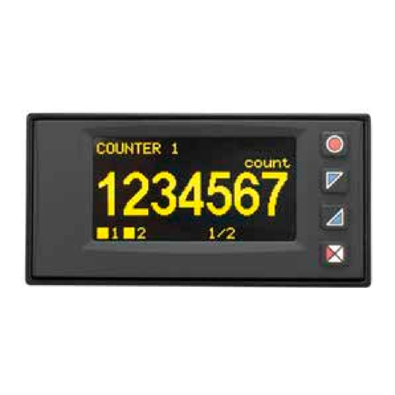
Page 17: Display And Key Functions
“1 val. per page” setting in the “Display -> Display” parameter. The inscription 1/12 at the bottom indicates that the first of 12 pages (maximum) used for the representation of enabled variables is being displayed. User manual - ZTA9648O - 17... - Page 18 13110.2 the data description and leaving only 4 1/4 the unit of measurement. This mode is enabled by setting the description of the relevant data item as a sequence of spaces (null description). 18 - ZTA9648O - User manual...
-
Page 19: Device Functions
Select the first variable to be to modify modified. The value to be the value. Through modified will be highlighted. it is possible to modify The edit menu substitutes digit-by-digit. the the navigation one. User manual - ZTA9648O - 19... -
Page 20: I/O Status
COM1. COM1 Serial Communication The ZTA9648O has serial COM1 (RS485) on which the Modbus RTU slave protocol is active. This allows the device to be connected to a supervisory system or more generally to a Modbus RTU master device. Each device will respond to a the Master only if it contains the same address as the one contained in the parameter Serial COM1 ->... - Page 21 The ZTA9648O can introduce a delay (in milliseconds) before responding to the master’s request. This delay must be set in the parameter Serial COM1 -> Delay responsive. For the complete list of parameters related to serial COM1, refer to the “Serial COM1” section in the “Configuration Parameter Table” chapter.
-
Page 22: Notes For Parameter Access
MNOP 0x41 ascii code “A” 0x42 ascii code “B” 0x4F ascii code “O” 0x50 ascii code “P” Modbus Read Description Reset value Address Write Device type EEPROM Software version EEPROM Address slave R/W EEPROM 22 - ZTA9648O - User manual... - Page 23 Serial command from counter 1 Indicates the value of the last serial command executed. Counter hold status 1 H (32 bit format, bit 31..16) Counter hold status 1 L (32 bit format, bit 15..0) User manual - ZTA9648O - 23...
- Page 24 Counter hold value 2 H (32 bit format, bit 31..16) Counter hold value 2 L (32 bit format, bit 15..0) Serial command counter 1 The commands available are those reported for word 620. Rate Meter value H Rate Meter value L 24 - ZTA9648O - User manual...
- Page 25 Counter counts 1 HH (64 bit format, bit 63..48) Counter counts 1 HL (64 bit format, bit 47..32) Counter counts 1 LH (64 bit format, bit 31..16) Counter counts 1 LL (64 bit format, bit 15..0) User manual - ZTA9648O - 25...
- Page 26 Counter value 2 LL (64 bit format, bit 15..0) Counter counts 2 HH (64 bit format, bit 63..48) Counter counts 2 HL (64 bit format, bit 47..32) Counter counts 2 LH (64 bit format, bit 31..16) 26 - ZTA9648O - User manual...
- Page 27 Bit 1 = Relais Q2 Bit 3 = Digital output Q4 Digital inputs status (0 = Off, 1 = Active): Bit 0 = I1 Bit 1 = I2 Bit 2 = I3 Bit 3 = I4 User manual - ZTA9648O - 27...
- Page 28 Parameter 1 (L)* R/W EEPROM 4003 Parameter 2 (H)* R/W EEPROM 4004 Parameter 2 (L)* R/W EEPROM 4597 Parameter 299 (H)* R/W EEPROM 4598 Parameter 299 (L)* R/W EEPROM 4599 Parameter 300 (H)* R/W EEPROM 28 - ZTA9648O - User manual...
- Page 29 Write Address 4600 Parameter 300 (L)* R/W EEPROM * Parameters changed using serial addresses 4001 to 4600 are saved in the Eeprom only after 10” from the last write of one of the parameters. User manual - ZTA9648O - 29...
-
Page 30: Error Messages
Detected an error in the read/write sequence of FRam memory. In all these cases, the device may no longer be able to function properly. Turn off and on again, if the problem persists contact the assistance. 30 - ZTA9648O - User manual... -
Page 31: Configuration
Sel to confirm modification. Press to exit without modify. 10.2 Loading default values Enter password 9999 to restore device factory settings. The device will restart to allow proper initialization. User manual - ZTA9648O - 31... -
Page 32: Reading And Configuration Through Nfc
RFID /NFC. No wiring required! The ZTA9648O is supported by the App Wachendorff EMG: using an ANDROID smartphone with NFC connection it is possible to program the device without using a dedicaded equipment. The App allows to read, set and backup all parameters which are stored into the internal memory of Wachendorff devices. -
Page 33: Configuration Through Memory Card
The ZTA9648O will show a restart request, necessary to update the configuration with the new written modifications; if it does not restart, the ZTA9648O will continue to work with the previous configuration. In addition to the classic operation of parameters reading->modification->wri- ting, Wachendorff EMG is provided with additional functions which can be accessed by the tab “EXTRA”, as save parameters / e-mail loaded values/ restore... -
Page 34: Loading Configuration From Memory Card
4 values per page As a consequence of setting this parameter, if more variables are used than can be displayed on a page, multiple pages will be used to complete the display of all values. 34 - ZTA9648O - User manual... - Page 35 30 seconds 30 minutes 1 minute 1 hour 2 minutes Data vis. n°1 Data vis. n°2 Data vis. n°3 Data vis. n°4 Data vis. n°5 Data vis. n°6 Data vis. n°7 Data vis. n°8 User manual - ZTA9648O - 35...
-
Page 36: Digital Input 1
Input suitable for sensors with Push-Pull output. Input suitable for sensors with line-driver output. Line-Driver This solution uses a pair of complementary signals read in differential mode for each input. Hardware filter Hardware filter Selects digital input hardware filter. 36 - ZTA9648O - User manual... -
Page 37: Digital Input 3
Input suitable for sensors with NPN output. Activation is initiated by short-circuiting the input to ground (0V) Input suitable for sensors with PNP output. PNP (Default) Activation starts by bringing a positive signal (+12/24 Vdc) to the digital input. User manual - ZTA9648O - 37... - Page 38 Z signal. Input when activated allows the loading of counter Counter charge 1 1 with its preset value. Counter charge 2 Input when activated allows the loading of counter 2 with its preset value. 38 - ZTA9648O - User manual...
-
Page 39: Counter 1
Counter count in Up (increment) mode I1 Up-I2 Off n + 4 comes from input I1. (Default 1) Input I2 remains free for n + 3 other uses. n + 2 n + 1 User manual - ZTA9648O - 39... - Page 40 +1 I1 L Counter count in Up I2 H (increment) mode I1 Up-I2 En/ derives from input I1. Input I2 enables or locks n + 3 (Lock) the counting n + 2 n +1 40 - ZTA9648O - User manual...
- Page 41 - 4 I1 L Counter count in Down I2 H (decrement) mode I1 Do-I2 En/ derives from input I1. Input I2 enables or locks (Lock) the counting n - 1 n -2 n - 3 User manual - ZTA9648O - 41...
- Page 42 - 2 n - 3 n - 4 Out Q1 Counter count in Up (increment) mode OutputQ1 n + 3 occurs each time output Q1 is activated. n + 2 n +1 42 - ZTA9648O - User manual...
- Page 43 Unit of measurement (Counter 1) Unit of measurement (Counter 2) Defines the counter unit text string (max. 5 characters) that will be displayed together with the counter value and its description. If you do User manual - ZTA9648O - 43...
- Page 44 6 decimal digits 0,000 3 cdecimal digits Automatic loading (Counter 1) Automatic loading (Counter 2) Selects the event that determines the counter automatic loading with the preset value. Disabled Automatic counter loading is disabled (Default) 44 - ZTA9648O - User manual...
- Page 45 Set4-Out duration 4 duration 4 (Counter = Set4-Out duration 4). Preset value (Counter 1) Preset value (Counter 2) Sets the value that is loaded onto the counter at each load event (Load). User manual - ZTA9648O - 45...
-
Page 46: Rate Meter 1
If you do not want to display the unit of measurement, set the text as a null string (5 spaces). “Hz ” (Default) 46 - ZTA9648O - User manual... - Page 47 Sets the value by which the measured frequency value is to be divided into a rescaled quantity useful for display. Set the correct divisor value that, associated with 1...99999 the Multiplier, allows a rescaled value to be obtained (Default 1) from the frequency value. User manual - ZTA9648O - 47...
- Page 48 This page allows these peaks to be reset to start a new acquisition. Disabled The peak display screen is not enabled. (Default) 48 - ZTA9648O - User manual...
-
Page 49: Output Q1
1 The data used to manage the output logic is the Counter 2 value of counter 2 The data used to manage the output logic is the Rate Meter 1 value of counter 1 User manual - ZTA9648O - 49... - Page 50 Output is active when Output Duration counter value is >= Counter Counts Value at the setpoint and Count>=- is deactivated when COUNTER Set*Od-C counter value is >= Load Value at setpoint + Output duration. Time Counter 50 - ZTA9648O - User manual...
- Page 51 Output duration (Output Q2) Output duration (Output Q3) Output duration (Output Q4) Defines the output activation duration. These parameters are only visible if the corresponding Source Value parameter is set to Counter 1 or Counter 2. User manual - ZTA9648O - 51...
- Page 52 Output mode (Output Q2) Output mode (Output Q3) Output mode (Ouput Q4) Defines the related output operation mode. These parameters are visible only if the corresponding Source Value parameter is set to Rate Meter 1. 52 - ZTA9648O - User manual...
- Page 53 Output results active Time within a band defined Inside band by the setpoint value Logic Output and the band Auto Clear by Input Clear by Input Latch Pulse Pulse duration time Pulse duration time User manual - ZTA9648O - 53...
- Page 54 Activation delay (Output Q2) Activation delay (Output Q3) Activation delay (Output Q4) Defines the output activation delay. These parameters are visible only if the corresponding Source Value parameter is set to Rate meter 2. 54 - ZTA9648O - User manual...
- Page 55 Setpoint value can be viewed in the user screens Visible only but changing the value is not allowed. Setpoint setting is only possible during configuration. Modifiable Setpoint value can be viewed and changed in the (Default) user screens. User manual - ZTA9648O - 55...
- Page 56 In the case of absolute setpoint, the value of the setpoint used to manage the output will be determined by the value of the setpoint parameter connected to the output, while in the case of relative setpoint, the value 56 - ZTA9648O - User manual...
- Page 57 Setpoint value (Output Q4) Defines the setpoint value related to output management. -9999999 .. Sets the setpoint value. The display of this number 9999999 takes formatting from the source quantity to which (Default 0) it refers.. User manual - ZTA9648O - 57...
-
Page 58: Output Setting
A voltage of 12 VDC is available at terminal 10. 12 VDC (Default) Outputs Q3 and Q4 provide this voltage when active. A voltage of 24 VDC is available at terminal 10. 24 VDC Outputs Q3 and Q4 provide this voltage when active. 58 - ZTA9648O - User manual... -
Page 59: Serial Com1
Answer delay Defines the minimum delay in ms, which the device introduces between the reception of the Modbus master’s query, and the beginning of th transmission of the reply. 0..100 ms (Default: 2 ms) User manual - ZTA9648O - 59... - Page 60 Note / Updates 60 - ZTA9648O - User manual...
- Page 62 Wachendorff Prozesstechnik GmbH & Co. KG Industriestrasse 7 • 65366 Geisenheim Tel.: +49 (0) 67 22 / 99 65 - 20 Fax: +49 (0) 67 22 / 99 65 - 78 E-Mail: wp@wachendorff.de www.wachendorff-prozesstechnik.de © Copyright by Wachendorff Prozesstechnik GmbH & Co. KG 2300.10.329-RevD-EN-Wachendorff 220923...
Need help?
Do you have a question about the ZTA9648O and is the answer not in the manual?
Questions and answers