Table of Contents
Advertisement
Quick Links
Operating Manual
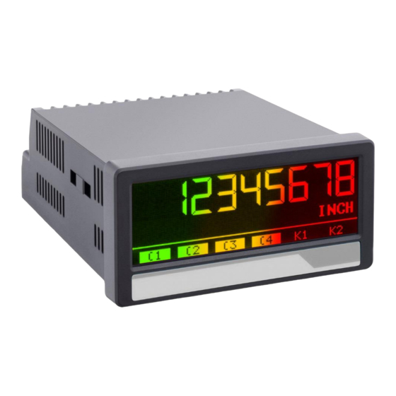
touchMATRIX Indicator WDG 053XIOM
SSI indicator for absolute encoders, with touchscreen and graphic display
Product features:
Master or Slave operation with clock frequencies up to 1 MHz
For single turn and multi turn encoders with SSI formats from 10 ... 32 Bit
Bright and high-contrast display with event-dependent color variations
Emulation of a 7-segment display inclusively icons and units
Intuitive and easy parameterization by plain text and touchscreen
24 V auxiliary output for encoder supply
Linearization with 24 control points
Numerous features, e. g. scaling, bit blanking etc.
3.78 x 1.89 inch norm panel housing and IP65 protection
Available options:
WDG 053XIOM*:
Option AC:
Option CO:
Wachendorff Automation GmbH & Co. KG – Industriestraße 7 – D-65366 Geisenheim – Tel.: +49 (0) 67 22 / 99 65 – 25 – www.wachendorff.de
Basic unit with SSI interface, 3 control inputs, 5 / 24 VDC encoder supply
Power supply 115 / 230 VAC
4 control outputs, serial RS232 interface
*WDG053XIOM only incl. option AC and CO available
Advertisement
Table of Contents

Related Manuals for Wachendorff touchMATRIX WDG 053XIOM


Summary of Contents for Wachendorff touchMATRIX WDG 053XIOM
- Page 1 Option CO: 4 control outputs, serial RS232 interface *WDG053XIOM only incl. option AC and CO available Wachendorff Automation GmbH & Co. KG – Industriestraße 7 – D-65366 Geisenheim – Tel.: +49 (0) 67 22 / 99 65 – 25 – www.wachendorff.de...
- Page 2 All contents included in this manual are protected by the terms of use and copyrights of Wachendorff Automation GmbH & Co. KG. Any reproduction, modification, usage or publication in other electronic and printed media as well as in the internet requires prior written authorization by Wachendorff Automation GmbH &...
-
Page 3: Table Of Contents
Table of contents 1. Safety Instructions and Responsibility ............4 1.1. General Safety Instructions ..............4 1.2. Use according to the intended purpose ..........4 1.3. Installation ................... 5 1.4. Cleaning, Maintenance and Service Notes..........5 2. Introduction ....................6 2.1. -
Page 4: Safety Instructions And Responsibility
1. Safety Instructions and Responsibility 1.1. General Safety Instructions This operation manual is a significant component of the unit and includes important rules and hints about the installation, function and usage. Non-observance can result in damage and/or impairment of the functions to the unit or the machine or even in injury to persons using the equipment! Please read the following instructions carefully before operating the device and observe all safety and warning instructions! Keep the manual for later use. -
Page 5: Installation
1.3. Installation The device is only allowed to be installed and operated within the permissible temperature range. Please ensure an adequate ventilation and avoid all direct contact between the device and hot or aggressive gases and liquids. Before installation or maintenance, the unit must be disconnected from all voltage- sources. -
Page 6: Introduction
2. Introduction The SSI display device is designed for panel mounting. It is universally applicable, with its intuitive operation, the extensive features and options. 2.1. Operation mode All functions are can be configured in the parameter menu. The device can be set to one of the following operation modes: •... -
Page 7: Electrical Connections
3. Electrical Connections The terminal screws should be tightened with a slotted screwdriver (blade width 2mm). 3.1. DC Power Supply The unit accepts DC supply from 18 to 30 V at the terminals 1 and 2. The power consumption depends on the level of the supply voltage with aprox. 100 mA and the additional current required at the Auxiliary Voltage Output. -
Page 8: Ssi-Inputs
3.3. SSI-Inputs At Terminal 5, 6, 7 and 8, the connection is available for SSI signals. The basic settings must be set in the menu SSI PROPERTIES. Wiring for MODE Master: Wiring for MODE Slave: WDG053XIOM _01c_oi_e / Aug-19 Seite 8 / 48... -
Page 9: Control Inputs
3.4. Control Inputs The three control inputs at terminal 10, 11 and 12 have HTL PNP characteristics. In the COMMAND MENU the programmable functions for the control inputs can be assigned. Available functions are: reset the display value, display switching, locking the touch screen or release the lock function of the control outputs. -
Page 10: Serial Interface (Option Co)
3.5. Serial interface (Option CO) A serial interface (RS232) is available at terminal 16, 17 und 18. This interface can be configured in the SERIAL MENU. The serial interface RS232 can be used: for easy setup and commissioning of the units ... -
Page 11: Ac Power Supply (Option Ac)
3.7. AC Power supply (Option AC) The device can be supplied with an alternating voltage between 115 and 230 VAC via terminals 24 and 25. The power consumption depends, among other things, on the level of the supply voltage and the setting and is approx. 3 VA, plus the encoder current taken from the auxiliary voltage output. -
Page 12: Display And Touch Screen
4. Display and touch screen 4.1. Screen structure for parametrization The parameter menus and the parameters are described in chapter 5. Start setup procedure: To edit the parameters, press the touchscreen for 3 seconds. Menu selection: Select the parameter menu via arrow buttons and confirm with “OK”. -
Page 13: Screen Structure In Operation
4.2. Screen structure in operation The following displays are available during operation. Depending on the device version and the selected operating mode, only certain representations are displayed. Display with unit and status bar To switch to the next display, press the touch screen. Control - status are only shown with Option Display single and muti-turn value: Display value for diagnostic purposes - raw... - Page 14 4.3. Error Message ERROR: MAXIMUM DISPLAY VALUE Display value is greater than + 99,999,999 ERROR: MINIMUM DISPLAY VALUE Display value is less than-99,999,999 ERROR: SSI ERROR BIT SET The error bit of the SSI encoder is set. In case of error, the measurement result is set to 0. With option CO the limit value monitoring is performed with the reference value "0".
-
Page 15: Parameter / Overview-Menu Structure
5. Parameter / Overview-Menu Structure This section provides an overview of the menus and their parameters. The menu names are printed bold and the associated parameters are listed under the menu name. Depending on the device version and the selected operation mode, only the necessary menus / parameters are shown. - Page 16 Menu / Parameter Menu / Parameter PRESELECTION VALUES SERIAL MENU PRESELECTION 1 UNIT NUMBER PRESELECTION 2 SERIAL BAUD RATE PRESELECTION 3 SERIAL FORMAT PRESELECTION 4 SERIAL INIT SERIAL PROTOCOL PRESELECTION 1 MENU SERIAL TIMER MODE 1 SERIAL VALUE HYSTERESIS 1 PULSE TIME 1 COMMAND MENU OUTPUT TARGET 1...
-
Page 17: General Menu
5.1. General Menu DISPLAY FORMAT This parameter selects the Display Format. The corresponding decimal point will be set automatically by display format 999999:59 or 9999:59:59. 99999999 Without format customization 999999:59 Display angle minutes / seconds 9999:59:59 Display in angle minutes : seconds FACTOR This parameter defines the factor with the result of the link will be charged. - Page 18 Continuation „General Menu“: SCALE UNITS (Anzeige Maßeinheit) This parameter defines the required engineering unit. This parameter does not affect the calculation of the display value. The number of decimal places must be defined with the parameter DECIMAL POINT. inch Default feet Stueck Grad...
- Page 19 Continuation „General Menu“: LINEARIZATION MODE This parameter defines the linearization function. See chapter 6.1. No linearization Linearization in the 1. quadrant QUADRANT Linearization in all 4 quadrants QUADRANT PIN PRESELECTION This parameter defines the PIN-code to lock the quick start of the menu PRESELECTION VALUE for entering the preselection values (master PIN 6079).
-
Page 20: Ssi Properties
5.2. SSI Properties MODE SSI setting master mode or slave MASTER Master-Mode: Clock for SSI encoder comes from the device SLAVE Slave-Mode: Clock for SSI encoder comes from the external master. ENCODER RESOLUTION Resolution of the SSI encoder (total number of bits) Smallest value Default value Highest value... - Page 21 Continuation „SSI Properties“: HIGH BIT (for bit blanking) Defines the highest evaluated bit (MSB) for bit blanking. If all bits should be evaluated, HIGH BIT must be set to the given total number of bit. Smallest value Default value Highest value LOW BIT (for bit blanking)) Defines the lowest evaluated bit (MSB) for bit blanking.
- Page 22 Continuation „SSI Properties“: SAMPLING TIME (S) Determines the read cycle for the SSI signal in the Master MODE 0.001 Minimum measurement time in seconds 0.010 Default value 9.999 Maximum measurement time in seconds ERROR BIT Defines the encoder monitoring and the error bit No error bit available.
-
Page 23: Preselection Values
Preselection Values This menu is used to set the preselection values or the switching points. The preselection values / switching points are always referred to the display value. This menu is only available for devices with option CO. PRESELECTION 1 Preselection / switching point 1 -99999999 Smallest value... -
Page 24: Preselection 1 Menu
5.3. Preselection 1 Menu This function is only available for devices with option CO. MODE 1 Switching conditions for preselection 1. Output/ display switches under the following conditions: Absolute value of the display value is greater or equal absolute value of PRESELECTION 1 With HYSTERESIS 1 not equal 0 the following switching condition is 0 |RESULT|>=|PRES|... - Page 25 Continuation „Preselection 1 Menu“: HYSTERESIS 1 This parameter defines the switching hysteresis of the switch-off point for preselection 1 No switching hysteresis … 99999 Switching hysteresis of 99999 PULSE TIME 1 (S) Duration of output pulse for the switching condition of preselection 1 0,000 No output pulse (static signal) …...
- Page 26 Continuation „Preselection 1 Menu“: START UP DELAY 1 (S) Start-up suppression for the switching condition of preselection 1. This adjustment is only valid for the switching condition |RESULT|<=|PRES| or RESULT<=PRES and mode SPPED and PROCESS TIME. (Start Up Delay 3 and 4 have an automatic start up suppression). 0.000 No start-up suppression …...
-
Page 27: Preselection 2 Menu
5.4. Preselection 2 Menu MODE 2 Switching conditions for preselection 2. Output/ display switches under the following conditions: See chapter PRESELECTION 1 MENU Trailing preselection 2: Display value is greater or equal to PRESELECTION 1 – PRESELECTION 2 RES>=PRES- TRAIL PRESELECTION 2 is the trailing preselection from PRESELECTION 1. -
Page 28: Preselection 3 Menu
5.5. Preselection 3 Menu MODE 3 Switching conditions for preselection 3. Output/ display switches under the following conditions: See chapter PRESELECTION 1 MENU Trailing preselection 3: Display value is greater or equal to PRESELECTION 4 – PRESELECTION 3 RES>=PRES- TRAIL PRESELECTION 3 is the trailing preselection from PRESELECTION 4. -
Page 29: Preselection 4 Menu
5.6. Preselection 4 Menu If the BATCH MODE is active, the batch counter is compared with the preselection value 4. MODE 4 Switching conditions for preselection 4. Output/ display switches under the following conditions: See chapter PRESELECTION 1 MENU Trailing preselection 4: Display value is greater or equal to PRESELECTION 3 –... -
Page 30: Serial Menu
5.7. Serial Menu This menu defines the basic settings of serial interface. This function is only available for devices with option CO. UNIT NUMBER This parameter defines serial device addresses. The addresses between 11 and 99 can be assigned to the devices. - Page 31 Continuation „Serial Menu“: SERIAL PROTOCOL Determines the sequence of characters send, when using the serial output for cyclic data transmission under time control (xxxxxxx = value SERIAL VALUE). Setting „1“ removes the unit address from the string which allows a slight faster transmission cycle. Transmission report = Unit Nr., +/-, data, LF, CR Transmission report = +/-, data, LF, CR SERIAL TIMER (S)
-
Page 32: Command Menu
5.8. Command Menu INPUT 1 ACTION (function Input 1) This parameter defines the function of the input “Ctrl. In 1”. No function Transfer of the currently acquired position value (after bit (d) (s) RESET/SET VALUE suppression and possibly performed encoder zero offset) in the parameter "SSI Offset"... - Page 33 Continuation „Command Menu“: INPUT 1 CONFIG This parameter defines the switching characteristics of the input “Ctrl. In 1”. ACTIVE LOW Active at „LOW“ (static) ACTIVE HIGH Active at „HIGH“ (static) RISING EDGE Activate at rising edge FALLING EDGE Activate at falling edge INPUT 2 ACTION This parameter defines the function of the input “Ctrl.
-
Page 34: Display Menu
5.9. Display Menu Parameter changes become active only after closing the menu selection. COLOR This parameter defines the display color. Event-depending change of the display color by a switching condition is possible (see PRESELECTION 1…4 MENU) Event-depending changes are only available for devices with option CO. 0 RED Red display 1 GREEN... -
Page 35: Linearization Menu
5.10. Linearization Menu The linearization function is defined in this menu. This menu will only be showed, if the LINEARIZATION MODE in GENERAL MENU is selected. Linearization description and examples are shown in the appendix. P1(X) … P24(X) X-coordinate of the linearization point. This value representing the display value which the unit show in the display without linearization. -
Page 36: Appendix
6. Appendix 6.1. Data readout via serial interface All codes shown in the parameter SERIAL VALUE are available for serial readout by PC or PLC. For communication the monitors use the Drivecom Protocol according to ISO 1745. To request for a data transmission you must send the following request string to the converter: EOT = control character (Hex 04) AD1 = unit address, High Byte... -
Page 37: Parameter / Serial Codes
6.2. Parameter / serial codes Menu Name Serial Code Default GENERAL MENU DISPLAY FORMAT GENERAL MENU FACTOR -99999999 99999999 GENERAL MENU DIVIDER -99999999 99999999 GENERAL MENU ADDITIVE VALUE -99999999 99999999 GENERAL MENU DECIMAL POINT GENERAL MENU SCALE UNITS GENERAL MENU LINIARIZATION MODE GENERAL MENU PIN PRESELECTION... - Page 38 Continuation „Parameterliste“: Menu Name Serial Code Default PRESELECTION 2 MENU MODE 2 PRESELECTION 2 MENU HYSTERESIS 2 99999 PRESELECTION 2 MENU PULSE TIME 2 (S) 60000 PRESELECTION 2 MENU OUTPUT TARGET 2 PRESELECTION 2 MENU OUTPUT POLARITY 2 PRESELECTION 2 MENU OUTPUT LOCK 2 PRESELECTION 2 MENU START UP DELAY 2 (S)
- Page 39 Continuation „Parameterliste“: Menu Name Serial Code Default COMMAND MENU INPUT 1 ACTION COMMAND MENU INPUT 1 CONFIG. COMMAND MENU INPUT 2 ACTION COMMAND MENU INPUT 2 CONFIG. COMMAND MENU INPUT 3 ACTION COMMAND MENU INPUT 3 CONFIG. COMMAND MENU COMMAND MENU COMMAND MENU COMMAND MENU COMMAND MENU...
- Page 40 Continuation „Parameterliste“ Menu Name Serial Code Default 137 LINEARIZATION MENU P15(X) -99999999 99999999 138 LINEARIZATION MENU P15(Y) -99999999 99999999 139 LINEARIZATION MENU P16(X) -99999999 99999999 140 LINEARIZATION MENU P16(Y) -99999999 99999999 141 LINEARIZATION MENU P17(X) -99999999 99999999 142 LINEARIZATION MENU P17(Y) -99999999 99999999...
-
Page 41: Linearization
6.3. Linearization The linearization function of this unit allows converting a linear input signal into a non-linear developing (or vice versa). There are 24 programmable x/y coordinates available, which can be set in any desired distance over the full conversion range. Between two coordinates, the unit uses linear interpolation. - Page 42 Application Example: The picture below shows a watergate where the opening is picked up by means of an incremental encoder. We would like to display the clearance of the gate "d", but the existing encoder information is proportional to the angular information φ. WDG053XIOM _01c_oi_e / Aug-19 Seite 42 / 48...
-
Page 43: Dimensions
6.4. Reading SSI-Value The received data is always filled to 32 bit data length. WDG053XIOM _01c_oi_e / Aug-19 Seite 43 / 48... - Page 44 6.5. Internal processing and calculation of SSI data WDG053XIOM _01c_oi_e / Aug-19 Seite 44 / 48...
- Page 45 Continuation „Internal processing and calculation of SSI data” WDG053XIOM _01c_oi_e / Aug-19 Seite 45 / 48...
- Page 46 Continuation „Internal processing and calculation of SSI data” WDG053XIOM _01c_oi_e / Aug-19 Seite 46 / 48...
- Page 47 6.6. Dimensions WDG053XIOM _01c_oi_e / Aug-19 Seite 47 / 48...
-
Page 48: Technical Specifications
6.7. Technical Specifications: Technical Specifications: Connections: Connector type: screw terminal, 1.5 mm² / AWG 16 Power supply (DC): Input voltage: 18 … 30 VDC Protection circuit: reverse polarity protection Consumption: approx. 150 mA (unloaded) Fuse protection: extern: T 0.5 A Power supply (AC): Input voltage: 115 / 230 VAC (60/50 Hz)
Need help?
Do you have a question about the touchMATRIX WDG 053XIOM and is the answer not in the manual?
Questions and answers