Table of Contents
Advertisement
Quick Links
Advertisement
Table of Contents

Subscribe to Our Youtube Channel
Related Manuals for Ambery IP-P4

Summary of Contents for Ambery IP-P4
-
Page 2: Rohs Information
RoHS information This product complies with RoHS specification. Safety information Caution Sign Please read carefully the notes and instructions in the manual to avoid any personnel injuries or device damages. Dangerous Voltage High voltage may exists in this product, so avoid touching. A triangle with flash sign and an arrow inside is to alert users the presence of uninsulated dangerous voltage within the product’s enclosure that may be of sufficient magnitude to... -
Page 3: Important Safety Instructions
Important Safety Instructions Please comply strictly with all the alarms and operation instructions in this manual and on the device, and keep this manual properly. Please do not operate this device prior to reading all the instructions on safety and operation. -
Page 4: Notices
Please do not attempt to maintain this device personally. Open the device enclosure may expose operators to dangerous voltages or other risks. Please contact dealers for relevant information. 11. Please avoid any items or liquids entering the device because their contact with dangerous voltage points or short-circuit parts may cause a fire or electric shock. - Page 5 Our factory hereby guarantees to users (buyers) that the product will be free from any defects due to material or manufacturing technologies within 1 year since being purchased During the warranty period and by virtue of the purchase proof, our factory will determine the reasons of any failures on its own to judge if the defect is caused by manufacturing technologies and/or materials.
-
Page 6: Table Of Contents
Content ROHS INFORMATION .......................... 2 SAFETY INFORMATION ........................2 IMPORTANT SAFETY INSTRUCTIONS ....................3 NOTICES ............................. 4 CONTENT ............................6 CHAPTER 1 PRODUCT INTRODUCTION ....................9 1-1 P ........................9 RODUCT NTRODUCTION 1-2 A ............................ 9 PPLICATIONS 1-3 P .......................... 10 RODUCT FEATURES 1-4 S .................... - Page 7 Overtime setting ......................... 24 Setting completion ........................25 4-3 S ............................25 IGN IN 4-4 M ............................ 25 AIN MENU CHAPTER 5 MONITOR ........................27 5-1 O ..........................27 UTLET ETTINGS Power setting ..........................27 Power Schedule ......................... 28 Network monitoring ........................28 Peripheral ............................
- Page 8 01 (01) H read IP-P4/P4S peripheral data................87 02 (02) Read IP-P4/P4S input current data................88 03 (03) read IP-P4/P4S output (outlet) data ................89 04 (04) Control IP-P4/P4S output (outlet): ................90 05 (05) read IP-P4/P4S build-in temperature data ..............91 ..........................
-
Page 9: Chapter 1 Product Introduction
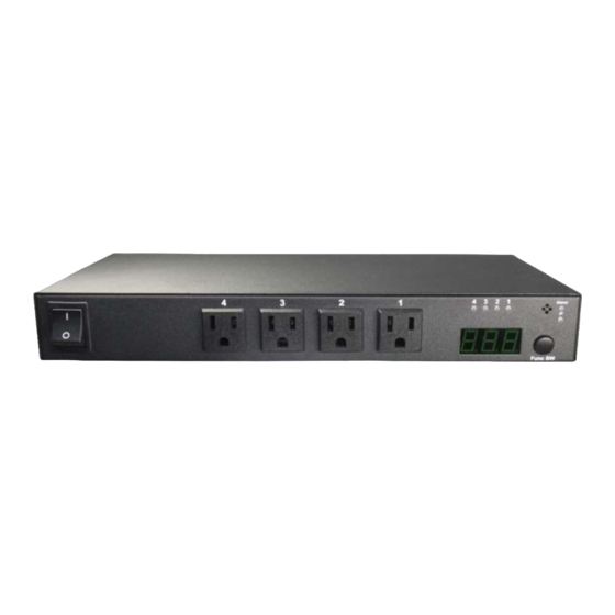
Chapter 1 Product Introduction 1-1 Product Introduction IP-P4/P4S is a web-based SNMP power control device integrated with versatile functions including power control, real-time current monitoring, power operation scheduling, remote web administration and power event alerts into one single unit. The unit helps system administrators and IT personnel to monitor and control their connected equipment and take preventive measures when needed. -
Page 10: Product Features
1-3 Product features Support HTTP/HTTPS to monitor real-time power consumption (PDU level) and control every outlet from remote sites. LED indicator showing output status of each port. LED digital panel display total current, the highest current and IP address. Circuit breaker to avoid damages caused by power overload. Power scheduling allows user to set up outlet actions periodically. -
Page 11: System Safe Shut-Down Requirements
1-4 System Safe Shut-down Requirements The computer BIOS connecting to the power outlet should support Wake on LAN or System after AC Back in order to smoothly turn on the computer power supply. Use windows operation system (XP, 2000 and above) in order to safely shut down the computer. - Page 12 RJ11 telephone jack USB port COM 2/1 Factory Reset button 2 Com Ports to enable terminal and API control, and 2 mutual cascading. Warning LED Indicator Circuit breaker Constant lighted: Abnormal, please call for your distributor. Device Operating LED Indicator Unit Power Inlet Slow-flashing: Normal.
-
Page 13: Chapter 2 Hardware Installation
Please power-off the device before installing. During installation, please follow the Important Safety Guidelines. 2-1 Horizontal Installation To install IP-P4/P4S in standard 19-Inch racks, please use L-shape brackets (optional accessory). Please lock on the brackets to IP-P4/P4S, and then fix IP-P4/P4S onto the rack. Chapter 2 Hardware Installation... -
Page 14: Connection Diagram
2-2 Connection Diagram Use the following diagram as reference to properly setup the device. Devices need to be managed Computer for accessing and managing RJ11 telephone jack RJ45 LAN port Com port RJ45 to DB-9F switch cable (optional) Power inlet Chapter 2 Hardware Installation... -
Page 15: Sync -Control
To execute sync-control, please follow the steps below: 1. Connect main power supply cable of the server to first IP-P4/P4S, set the UART (RS232) type as Daisy Chain. -
Page 16: Chapter 3 Panel Operation
Chapter 3 Panel operation This chapter will introduce how to check total current and IP address through Func SW as well as the meanings of each part of LED panels. 3-1 Panel description Outlet LED Indicator When the LED is lit, it means the outlet status is on, or otherwise off. - Page 17 LED panel Display total current, max current and IP address. Func SW button Switching: To switch among total current, max current and IP address to be displayed on the LED panel. Setting: Hold the button for 3 seconds under total current mode to enter alarm current setup mode.
-
Page 18: Total Current And Ip Operation
3-2 Total current and IP operation The first mode of LED is total current, switching with Func SW to show in a regular turn of total current, max current and IP as below: When LED shows the maximum total current record hold the Func SW key for 3 seconds with a long beep to zero the maximal current records. -
Page 19: Chapter 4 First Operation
Chapter 4 First Operation In this section users will learn how to query devices IP and how to set language, account password, network and time zone through daemon. 4-1 Network connection (Assign Device IP) (The default device IP is 192.168.1.10). To have the device automatically receives a DHCP IP address, connect the Ethernet port to the network first, then, power on the device. -
Page 20: Language
Language Currently available in English, Traditional Chinese, press Next to continue. Account Setting This menu is for setting the admin account and password of the device, all the fields should be filled in. Press NEXT to continue. Chapter 4 First Operation... -
Page 21: Host Setting
Host setting By default, the product is assigned dynamically (DHCP). To specify a fixed IP address, please fill in IP Address, Subnet Mask and Gateway DNS setting Key in the DNS server, provided by ISP providers, then, you can set up two DNS servers. -
Page 22: Web Server
Web Server When you link the Net via browser (ex. IE) to PDU remote power control, you may have two ways: one is the usual way – HTTP, the other is a security measure – HTTPS. Comment setting-- rolling down for Http or, Https as concern transmissions. -
Page 23: Time Server Setting
Time Server Setting User can setup device time synchronize with Time Server. Sync with time server: When this option enabled, device time will synchronize with time server. Time Server: Please fill in time server IP address or click to select time server option list. -
Page 24: Time Zone
Time zone Please fill in the time zone where the device is. The system is based on Greenwich Mean Time, thus; an accuracy setting to time zone may affect the time record of events and chart. Time Format Select the time format to show in the system. Overtime setting You may set up operational overtime in this section. -
Page 25: Setting Completion
Setting completion Press finish and equipment will automatically reboot to update configurations. 4-3 Sign in It will show a fixed IP Address after rebooting (User can see IP address through LED panel as enabled DHCP, See 3-2 Total current and IP operation First time login, please key in the default account and password: admin, admin, and click Confirm. - Page 26 menu, each part of which is illustrated as below: User login information Automatically logout Timeout System Logout Select Tap Operation block Next chapter will introduce each operation Chapter 4 First Operation...
-
Page 27: Chapter 5 Monitor
Chapter 5 Monitor At MONITOR tab, users can operate power switch and set up relevant peripheral parameters to each outlet. 5-1 Outlet Settings Power setting Power setting list is mainly for setting the relevant information of power on/off of all lines. Name: Description of each power outlet. -
Page 28: Power Schedule
Default:You may set preset switch status when local power was lost and come back again. The statuses in drop down list are 1.ON, 2.OFF, 3 Last statuses before power lost. Power Schedule In this page to create power schedule to every outlet on/off by time. Cycle: Set up working cycle of power outlet. -
Page 29: Peripheral
Ping: Enable / Disable network detection. Host: Network device address to be detected. Ping Interval Time (Min): Execute the time interval of PING network devices. Ping Times (Detection frequency): Frequency of continuous abnormality during Ping network device, when the detected Ping failure frequency exceeds this set value;... - Page 30 Value: The device would command the order as temp reach this value. Duration: The duration of value that compliance with the peripheral conditions. After clicking the icon “X”, it would pop up a confirm window; Delete: your condition would be delete, to command device please reset the command.
- Page 31 two: Add new name with “Alarm 2,” Example Condition one: If device temp set higher than 50℃ ( > 40℃), and last 2sce (Duration 2sec) then it will perform action On. ※ All of the new created terms in the same peripheral should matched or device will not follow the setting.
-
Page 32: Copy
Copy To quickly set up the power outlet parameter of each line, after setting the first line, the parameters can be copied to other lines of power outlet. Parameter drop-down menu: allow to copy parameters such as power source setting, safe shutdown, work schedule, network detection, current monitoring and peripheral. -
Page 33: Turn On Ups Functions
Turn on UPS functions To let the functions show up, please go to system > Serial Port > UPS, and do as following; clicks save to continue. Press Save and equipment will automatically reboot to update configurations. Chapter 4 First Operation... - Page 34 UPS tap would show up in Power Monitoring Tab. ※ Not all surveillance UPS will show the information of all fields. UPS Information Product Model: Display the current UPS device model. Online State: Display the concatenated state of UPS device, there are two states: "normal"...
- Page 35 Output Information Output Battery Supply: Display the current UPS device is power by AC or battery Output voltage: Display the voltage of the output current UPS device. Output frequency: Display the frequency of the output current UPS device. Output current: Display the current of the output current UPS device. Electrical Load: Display the electrical load value of the device concatenated with the output of the present UP device, unit: %.
-
Page 36: Chapter 6 System Setup Menu
Chapter 6 System Setup Menu In this web page, users can set Network, Email server, Message server, SNMP, SysLog, IDCView, Serial Port, Peripheral parameters, and other relevant data. 6-1 Network setting This menu is mainly for setting the basic data of network. Enabled DHCP: Use checkbox to enable DHCP. - Page 37 Primary DNS Server: Configure the IP and DNS server addresses for Network Adapter 1. Secondary DNS Server: Configure the IP and DNS server addresses for Network Adapter 2. Enabled Http: Allow browser to connect with smart monitor by HTTP. Enabled Https: Allow browser to connect with smart monitor by HTTP SSL.
-
Page 38: E-Mail Server
6-2 E-mail server When there is a triggered warning from the setup of this power switch, this device will send alert message to the preset email accounts. Host: It is the Host IP address of the e-mail sending an alarm e-mail when an event occurs. - Page 39 Email Test: After set up the above info, you can send a test mail to make sure this function is normal. Click Test, the window will pop up as below: 'Send To' Address: Enter the EMAIL address for test. Contents: Enter the message for test.
-
Page 40: Sms Server
6-3 SMS server In this section, user can set up the warning message and info to the SMS server. The protocol here has being supported by many SMS suppliers’ (ISP) API. System will send out account, password, time, and related info via HTTP to the SMS server of ISP supplier or preset SMS server. - Page 41 @@DEVICENAME@@ : The device name to show as sending a message. @@ACCOUNT@@ : The account to send the message. @@PASSWORD@@ : The password to send the message. @@GSMNUM@@ : The number to send the message. @@MSG@@ : Message content to show as sending a message. @@IP@@ : Device IP to show as sending a message.
- Page 42 Phone Number: Enter your cell phone number for testing. (@@GSMNUM@@) Content: Enter the message for testing. (@@MSG@@) Test: Test result will be displayed at the black area after pressed test button. Please press “Confirm” to save setup when finish. Chapter 6 System Setup Menu...
-
Page 43: Snmp Setting
6-4 SNMP setting You can setup SNMP Agent and SNMP Trap in this page. SNMP v1 / v2c Agent Enabled v1 / v2 SNMP: Enabled SNMP v1 / v2 Agent. SNMP Port: Enter Set the destination port. Default is 161. Read Community: Key in passwords for the Community Name fields. - Page 44 Type: There are two types: Read Only, Read and Write. Authorization type: There are two types: MD5 or SHA. Authorization password: The password of authorization type. Private type: There are two types: No or DES. Private password: Private type password. SNMP Device info sysName: The name displayed on SNMPAgent.
-
Page 45: Syslog Record
Host: Enter the Host IP address of SNMP Trap Server for testing. Port: Enter SNMP Server connect port. Default is 162. Authority String: The authentication string to access SNMP Trap. Contents: Enter the message for testing. (English and Number only) Test: Test result will be displayed at the black area after pressed test button. - Page 46 Host: Enter Syslog Server Host IP. Port: Enter Connect Port for Syslog Server. Default is 514. Press Add button to build new data. User can press Delete button to remove exist data. Please click Save to store setup data. Syslog Test: After set up the above info, do the reference to make sure this function is normal.
-
Page 47: Serial Port (Uart)
6-6 Serial Port (UART) RS232 This menu is mainly for setting the data of COM 1 (UART 1), COM 2 (UART 2). Serial Port 1 Kind: There are four UART types: Disable, Console, API and UPS as described below. Disable: Cancel UART function. Console: Computer connects with the device through RS232 and operate the device through terminal program API: other devices can operate the current device through API protocol. - Page 48 Type: APC Smart UPS and Winpower are available. Model: Press "Search", system will detect UPS model, and show in the blank. Bob rate: Set UART Bob rate parameter. Bit: Set UART bit parameter. Parity check: Set UART Parity Check parameter. Stop Bits: Set UART stop bit parameter.
- Page 49 Type: APC Smart UPS and Winpower are available. Model: Press "Search", system will detect UPS model, and show in the blank. Bob rate: Set UART Bob rate parameter. Bit: Set UART bit parameter. Parity check: Set UART Parity Check parameter. Stop Bits: Set UART stop bit parameter.
-
Page 50: Peripheral Parameters
Re-search: If the model number is blank, confirm if the device is connected and search again. 6-7 Peripheral Parameters This menu is mainly for setting current, tolerance ranges of temperature and humidity, power statistics, probe as well as the Panel operating etc.. Ring Count: ... -
Page 51: Other
6-8 Other This menu is mainly for setting device web page language, operation timeout and device date format. General Setting Language:Traditional Chinese, Simplified Chinese and English. "System" Timeout (Min):This is the lasting time that the device will logout automatically with no operation is processing. Format:Choose equipment time format. -
Page 52: Chapter 7 Firewall Menu
Chapter 7 Firewall menu In this tab, you may set up permitted IP or Mac address to access this remote power manager. 7-1 IP Filter User can set up permitted IP section in this page. Enabled IP Filter: Allow authorized IP address to access this device. Allowed IP Address: After key in permitted IP section;... - Page 53 Allowed MAC Address: Enter permitted MAC number. Please click ADD to implement this action. To delete a specific IP address, please clicks “X”. ※ MAC blocking feature is only available for local area network; if a router is used, the original adapter MAC address may be changed. Chapter 7 Firewall menu...
-
Page 54: Chapter 8 Account Management
Chapter 8 Account Management This menu allows the administrator to setup 40 sets (max) of authorized user accounts. It can ADD, Modify and Delete the User account. 8-1 New User When you click Add, browser will pop up a window for you to set Account, Password and User Type. -
Page 55: Outlet Authority
General: Only Switch control is permitted, but not authorized to change system settings. Manage: Parameter setting is permitted, and controllable switch can be changed. Administrator: Administrator can manage the whole network. 8-2 Outlet Authority Outlet Authority tab is mainly to open up outlet authority to other users Outlet Authority: It is to grant the authority to created user(s) to manage the controllable ports by clicking the checkboxes. -
Page 56: Email
8-3 Email System would send email to the user when alarm occurred. User can select the receiving contents. Enable alert: Check means user wants to receive e-mail alarm. ‘Send’ To: Receiver’s e-mail address. Parameter: Check to enable warning as alarm occurred. Infeed: Check to enable warning as abnormal condition of infeed occurred. -
Page 57: Sms
8-4 SMS System would send SMS when alarm occurred. Enable alert: Check means user wants to receive SMS alarm. Cellphone: Receiver’s cellphone number. Parameter: Check to enable warning as alarm occurred. Infeed: Check to enable warning as abnormal condition of infeed occurred. Outlet Control: Check to enable warning as abnormal condition of switch operation occurred. -
Page 58: Modify Account
8-5 Modify Account Click this icon, , to modify the previous setting. Operation of Alarm, please see 8-1 Add New Account. 8-6 Delete Account Click Delete icon; browser will pop up a Confirmation of delete window. Click Confirm; this Account cannot be utilized any longer. Chapter 8 Account Management... -
Page 59: Chapter 9 Time
Chapter 9 Time You can setup the time server at this page. System Time / Device Time:Date and time of the system Time Synchronization Time Synchronization:You may either rolling down to select Sync with computer or Manual Setting. Time Server Setting Synchronization with Time Server:Select this time method if you want the system time of this power switch to be the same as Greenwich Mean... - Page 60 Time Server List:You may have numerous options to select time server as this device provides, then, click Save to finish it. Time Zone:The time here is following Greenwich Mean Time as most NTP servers do. User must adjust the time to be the same with local time. Chapter 9 Time...
-
Page 61: Chapter 10 Event
Chapter 10 Event The web page supports to query the recent 200 logs, including the time, types and reasons of such logs. Click on icon, , to list all events by order. The meaning of three icons is as Refresh, Download and Delete. Refresh: Click Refresh button to refresh the screen. -
Page 62: Chapter 11 Firmware Upgrade
Chapter 11 Firmware Upgrade This web page is about firmware upgrade and configuration files. 12-1 Firmware Upgrade The upgrade steps are as follows: Step 1: Press "Browse". Step 2: Select the directory of the firmware update files, and then press "Open". Step 3: Press "Upgrade"... -
Page 63: Save/Update Profile
Upgrade will finish after 100 seconds. When the file you selected is not the correct firmware file, the following window will be displayed: 11-2 Save/Update Profile The steps for saving profiles are as follows: Step 1: Press "Save". Step 2: Save the files to the directory specified by you. Chapter 11 Firmware Upgrade... - Page 64 The steps for upgrading profiles are as follows: Step 1: Press "Browse". Step 2: Select the directory of the configuration files, and then press "Open". Chapter 11 Firmware Upgrade...
- Page 65 Step 3: Through the function of Upgrade Profiles, press "Upgrade", the web page will upload profiles, and then enter the menu of Profile Upgrade, and then profile upgrade finished after countdown. When the file you selected is not the correct profiles, the following window will be displayed: Chapter 11 Firmware Upgrade...
-
Page 66: Chapter 12 Console Operation
2-3 product installation). 12-1 Online Set ①Using build in Hyper-terminal or similar programs to IP-P4/P4S Console; Related parameter setting of terminal program Comport should be the same with UART1 set values (For UART 1 related parameters, see 6 - 6 UART). - Page 67 ③After entering finished, operation menu will be displayed to control power switch and set network data. Chapter 12 Console Operation...
-
Page 68: Power Control
Operation method of the menu is as follows: 1. Press ↑ or ^W can drift the menu, >> drift upward. 2. Press ↓ or ^Z can drift the menu, >> drift downward. 3. Press → or ^D can select the data of the next menu. 4. -
Page 69: System Preferences
12-3 System Preferences After select the menu of "SYS" from the main menu, press → or ^D to enter System Preferences setting. Chapter 12 Console Operation... -
Page 70: Network Preferences
12-3-1 Network Preferences After select the menu of "NetWork" from the main menu, press → or ^D to enter System Preferences setting. DHCP: Press "Space" key to enable the device IP to be assigned by DHCP server or not. Address: Set the address IP of the network connecting with this device. Subnet Mask: Set the network mask of this device. -
Page 71: Account Preference
Https Open: Enable this means allowing browser using Http SSL to connect to the device. Move the cursor to the network data to be revised, press ^X or ^L to leave the menu after completion. 12-3 -2 Account Preference After select the menu of "Account" from the main menu, press → or ^D to enter System Preferences setting;... -
Page 72: Firewall Preference
12-4 Firewall Preference After select the menu of "Firewall" from the main menu, press → or ^D to enter System Preferences setting. Filter: Press "Space" to enable IP filter or not. Filter: Press "Space" to enable MAC filter or not. Move the cursor to the filter data to be revised, press ^X or ^L to leave the menu after completion. -
Page 73: Reload Preference
12-5 RELOAD Preference After select the menu of "RELOAD" from the main menu, press → or ^D to enter the query windows to reload all data, if yes, press "Y" then the device will reload network, user and firewall data, and the data revised on the terminal before will be canceled. -
Page 74: Parameter Saving
12-6 Parameter Saving After select the menu of "SAVE" from the main menu, press → or ^D to enter the query windows to save and reboot the device, if yes, press "Y" then the device will save the revised data and reboots. Chapter 12 Console Operation... -
Page 75: Log Out
12-7 log out After select the menu of "LOGOUT" from the main menu, press → or ^D to enter the query windows, if press "Y" then the terminal program will be logged out and the sign-in menu will be displayed. Chapter 12 Console Operation... -
Page 76: Chapter 13 Ip Search Utility
Chapter 13 IP Search Utility 13-1 Windows You can learn how to search the product information reset IP address and enabled or disabled DHCP by using IP Search Utility. As the system is transfer from UDP, you may not seek the IP address by the browser. When IP Search Utility is proceeding, it will pop up as below: Adapter: You may have to assign the packet of device. - Page 77 Open:”True” means, allow browser to connect with this device by Http Http. Http Port:Provide browser to communicate by HTTP with this device. Open:”True” means, allow browser to connect with this device by Https Http SSL. Https Port:Provide browser to communicate by Http SSL with this device.
-
Page 78: Java
13-2 Java You can learn how through multi-version (eg. Windows、MAC、Linux) to search the product info, reset IP address and enabled or disabled DHCP by using IP Search Utility of Java. As the system is transfer from UDP, you may not seek the IP address by the browser. When IP Search Utility is proceeding, it will pop up as below: Adapter: You may have to assign the packet of device. - Page 79 MAC: MAC of this device HttpOpen:”True” means, allow browser to connect with this device by Http. HttpPort:Provide browser to communicate by HTTP with this device. HttpsOpen:”True” means, allow browser to connect with this device by Http SSL. HttpsPort:Provide browser to communicate by Http SSL with this device. Modifying data section:To display and modify the info of network, edit space instruction is shown as below:...
-
Page 80: Appendix
Appendix Set back to factory default values Users who forget the network account and password of the product can press "Reset" to recover to the factory default values, and the device will be rebooted at the same time. 1. Press and hold "RESET" more than 3 seconds, Red LED will start flashing, and release "Press"... -
Page 81: Http Message Api Example
HTTP Message example A Message API example of a message service provider is given as below. The transmission mode is Get in TTP protocol, and the URL format is as follows: http://smsip/httpsms.php?Tag=Value&Tag=Value&Tag=Value… Tag variable list: Required/optional Tag Description Required depid Company Code Required username... -
Page 82: Message Format Explanation 1
@@DEVICENAME@@ : The device name to show as sending a message. @@ACCOUNT@@ : The account to send the message. @@PASSWORD@@ : The password to send the message. @@GSMNUM@@ : The number to send the message. @@MSG@@ : Message content to show as sending a message. @@IP@@ : Device IP to show as sending a message. -
Page 83: Http Api Example
User's password Required (password=@@PASSWORD@@)& Cellphone number Required (dstaddr=@@GSMNUM@@)& This format is Device IP & Message content changeable with the (smbody=@@IP@@,@@MSG@@) content. The message will automatically change as the even change. Remove @@IP@@, means device IP info will not reveal in message content. - Page 84 Output (Outlet) Control Kind Code Table: Value Description Output (Outlet) on Output (Outlet) off Output (Outlet) Reboot Output (Outlet) Reboot Data back-transmission format is as follows: {"OutCtrl":[{"Id":value,"Ret":value,"RetStr":""},…]} List of variables: Domain Name Description Control ed Output (Outlet) Line On/off status, for the relevant data, see Output (Outlet) Status Code Table Output (Outlet) Status Code Table:...
-
Page 85: Rj45-To-Db 9 Cable
RJ45-to-DB 9 cable Because the ComPort of this product uses RJ45 connector, thus a RJ45- to-DB 9 cable is needed in order to connect with the computer ComPort. The pins of RJ45-to-DB 9 cable are corresponding to different parts as described below: 9-pin D-Sub female connector RJ45 connector... -
Page 86: Uart Api Protocol
UART API Protocol 1. Hardware Interface: UART 2. Package format Start Function Data 2 chars 0 up to 2x16 char(s) 2 chars 1 chars char LRC = ~( Function + Data) ~: index value reverse Example: 02 (decimal) = 00,000,010 (binary) ~ (00,000,010 ) = 11110010 = 0 xFD (hexadecimal) 3. -
Page 87: 01) H Read Ip-P4/P4S Peripheral Data
01 (01) H read IP-P4/P4S peripheral data Request: Domain Name Bytes Description Function Code Function code: 01 H Respone: Domain Name Bytes Description Function Code Function code Model Product Model Infeed Total Number of input power Infeed Kind Kind of input power... -
Page 88: 02) Read Ip-P4/P4S Input Current Data
02 (02) Read IP-P4/P4S input current data Request: Domain Name Bytes Description Function Code Function code: 02 H Infeed Id Number of Lines Respone: Domain Name Bytes Description Function Code Function code: 02 H Infeed Id Number of Lines Infeed Total Current... -
Page 89: 03) Read Ip-P4/P4S Output (Outlet) Data
03 (03) read IP-P4/P4S output (outlet) data Request: Domain Name Bytes Description Function Code Function code: 03 H Out Id Number of Lines Respone: Domain Name Bytes Description Function Code Function code: 03 H Out Id Number of Lines Out Switch Stataus... -
Page 90: 04) Control Ip-P4/P4S Output (Outlet)
04 (04) Control IP-P4/P4S output (outlet): Request: Domain Name Bytes Description Function Code Function code: 04 H Out Id Number of Lines Ctrl Kind The types to be controlled, for the relevant data, see Output (outlet) Control Kind Code Table... -
Page 91: 05) Read Ip-P4/P4S Build-In Temperature Data
Control the data of output (outlet) line 1: LRC = F 9 = ~ (04 + 01 + 01) Send: 040,101 F 9 (CR) Recv: 040,101 F 9 05 (05) read IP-P4/P4S build-in temperature data Request: Domain Name Bytes Description... -
Page 92: Product Information
Product Information Specifications IP-P4/P4S IP-P4/P4S (NEMA5-15R/Universal) Outlet/Socket Max. Output Current Voltage 100V-120V Power consumption 50 - 60 HZ Operating temperature 0 - 60℃ 0 - 90% Operating Humidity -25 - 65 °C Storage temperature (-13 - 149 °F ) Rack form...
Need help?
Do you have a question about the IP-P4 and is the answer not in the manual?
Questions and answers