Table of Contents
Advertisement
Quick Links
Advertisement
Table of Contents

Related Manuals for RUiXU RX-LFP48100-H

Summary of Contents for RUiXU RX-LFP48100-H
- Page 1 Rechargeable Lithium battery Operation and Maintenance manual Version: V1.4...
- Page 2 This manual describes in detail the requirements and procedures for safe installation and operation of RUIXU lithium battery pack. Please read this manual carefully, only qualified persons are allowed to install, operate and maintain the system, otherwise it may cause product damage or personal safety risks.
-
Page 3: Table Of Contents
Content 1. Information ................................4 1.1 Validity ................................4 1.2 Target Group ............................... 4 1.3 Levels of warning messages ........................4 1.4 Symbol Description ............................ 5 1.5 Abbreviation Description ..........................6 2. Safety ..................................7 2.1 Safety precautions ............................7 2.2 Safety instructions ............................ -
Page 4: Information
1. Information 1.1 Validity This document is valid for RX-LFP48100 / RX-LFP48100-H battery system. The content mentioned in this manual for RX-LFP48100 also applies to RX-LFP48100-H.The RX-LFP48100-H supports the Heating during charging, which will be explained separately in Appendix II. -
Page 5: Symbol Description
permanent damage. Indicates a situation which, if not avoided, can result in property damage or product not work or accelerated product damage 1.4 Symbol Description 1.4.1 Symbols on products label Label Definition Beware of electrical shock Do not place the battery within children/pet touchable area. Do not place the battery near heat source and flammable material Do not expose the battery to direct sunlight, rain and snow. -
Page 6: Abbreviation Description
The certificate label for U.K EMC directives Recycle label WEEE designation 1.4.1 Other symbols Label Definition Indicates activities that can only be performed by qualified persons Grounding point 1.5 Abbreviation Description Abbreviation Definition Battery/battery pack/battery module Single RX-LFP48100 rechargeable lithium iron phosphate battery pack including cells, BMS and enclosure etc. -
Page 7: Safety
2.2 Safety instructions The battery has been designed and tested in accordance with international (such as UL, IEC, UN38.3 etc.) safety requirements. However, Due to various factors during the whole lifetime process, RUIXU cannot Version: V1.4 Page 7 of 31... -
Page 8: Safety Gear
guarantee absolute safety, in order to prevent personal injury and property damage and ensure long-term operation of the battery, please do read and following the below section carefully to operate the battery and handle emergency situations. 2.2.1 Safety gear It is required to wear the following safety gear when installing and handling the battery pack. Insulated gloves Safety Glasses Safety Shoes... -
Page 9: Other Tips
2.2.3 Other Tips • All the product are strictly inspected before shipment, please contact us for replacement if you notice there’s any defectives such as swelling. • Do not disassemble batteries and components, otherwise the manufacturer will not be responsible for any damage caused by unauthorized disassembly or repair. -
Page 10: Product Overview
3. Product Overview 3.1 Introduction The RX-LFP48100 battery is designed for residential application and works as a storage unit in the photovoltaic system. It is a 48V Li-ion battery storage system, with BMS inside itself. It could be operated in both on-grid, back-up and off-grid modes with compatible inverters. Below is the general schematic of an ac-coupled system. -
Page 11: Features
3.2 Features • Highest safety, battery is made from LiFePO4 chemistry and comply with highest international safety and transport standard. • Modular and flexible, support up to 32 batteries connect together to expand the system energy. • Build-in pre-charge circuit to avoid rush current when connecting with different inverter/chargers. •... -
Page 12: Specification
3.3 Specification 3.3.1 Dimension 3.3.2 Parameters Items RX-LFP48100 Rated voltage 51.2V Max. voltage range 44.8~57.6V, Shipping voltage>51.2V Charge voltage 56.0V Float charge voltage 54.6V Low voltage cut-off 44.8V Nominal energy 5.12KWh Usable energy 4.92kWh Nominal capacity 100Ah Dimension 482*133.5*460mm (18.9*5.2*18.1 inch) Weight ~50kg (110lb) ≤50A... -
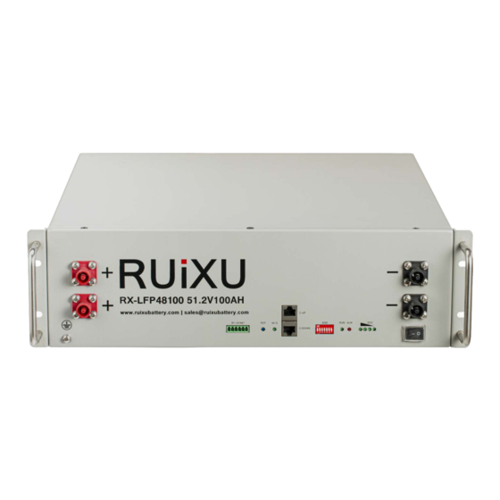
Page 13: Panel Interface
Max parallel number 32pcs Operation temperature Charge: 0~50℃ Discharge:-20~50℃ <6 months 0℃<T<30℃ Storage temperature <3 months -10℃<T<45℃ Recommended environment 15~35℃, 5~75%RH The optimum operating temperature range is from 15°C to 30°C, Frequent exposure to the harsh temperatures may worsen the performance of the battery pack and cycle life. 3.3.3 Panel Interface No. - Page 14 Used to set the RS485 baud rate and inverter protocol choosing Used to show battery is in running status when lighting or flashing Used to show battery Alarm/Protection status Used to show battery real-time SOC Power switch Used to Power on/off battery Negtive terminal Used to connect the inverter/charger Mounting ear...
- Page 15 Sol-Ark/Solis/Goodwe/Deye/Growatt/SAJ/LUXPOWER Megarevo/INVT/Sermatec/TBB/MUST/Sunsynk Schneider Fail to follow the DIP switch setting will cause the communication fault between battery and inverter, for more detail setting with different inverter/charger, please contact your supplier or RUIXU for consultation. Version: V1.4 Page 15 of 31...
-
Page 16: Protection
3.3.3.4RUN/ALM/SOC Normal/Alar LED indicator Mode m/Protectio description ● ● ● ● ● ● Shutdown Dormancy ALL OFF Normal FLASH1 Standby According to battery state of Standby Warning FLASH1 charge Low voltage According to battery state of All alarm Normal charge (highest SOC LED: except the over Warning Charge... - Page 17 Cell/PACK low- under the protection value and it will be released only when all recovery. Please charge voltage the cell voltage back to the release voltage range or there is timely, otherwise it may efficient charge current be in Low-power mode to be over-discharged.
-
Page 18: Installation
4 Installation 4.1 Preparation 4.1.1 Safety Compliance The system installation must be finished by qualified person(s), During the whole installation process, please strictly follow the local safety regulations and related operating procedures. 4.1.2 Environment The operating environment shall meet the following requirements: Category Description -10℃-50℃(maximum operating range) -
Page 19: Inspection
4.2 Inspection 4.2.1 Unpack precautions Please load and unload it in accordance with the specified requirements to prevent sun and rain when you receive the equipment. Please check and confirm the goods (such as quantity, appearance, etc.) according to the "scope of delivery "... -
Page 20: External Cable Kits
4.2.3 External cable kits Cables connected to inverter or junction box belongs to an External Cable kits, NOT include in battery carton. Customers need buy it separately, the information are as below. Type Detail Qty. External bus cable 2pcs (2000mm) Grounding cable 1pcs Inverter... -
Page 21: Start Installation
Keep the unused cable pins NULL to avoid affecting the closed loop communication. A ground connection of communication cable may be required from some inverters, please follow the rules from inverter manufacture. 4.3 Start Installation 4.3.1 Remainder Please check again the following conditions or equipment whether meet the requirements before installation: ... -
Page 22: Cable Connection And Commissioning
4.3.2.1 Rack mounted Take the battery pack out from carton. Get the Rack ready and place it horizontally at a reasonable location. iii. Place the battery on the rack or cabinet tray via manual-lift, Insert the screws and fasten the battery to the rack or cabinet. -
Page 23: Get Battery Ready
5.1 Get battery ready 5.1.1 Ensure all the battery is in OFF mode, and confirm the installation is tighten and stable. 5.1.2 Check the number and specification of cable kit accessories are correct according to the Scope of delivery item, if you are making cable yourself, please follow manufacturer's requirements. 5.1.3 Switch on all battery individually, check whether there is any alarm/protection information, if yes, turns to troubleshooting. -
Page 24: Communication Cable Connection
5.3 Communication cable connection 5.3.1 Take out battery to battery communication cable. 5.3.2 Confirm the location of Master battery, insert the RJ45 plug into the Link Out port and connect the other side to next battery Link IN port, daisy chained all batteries. Version: V1.4 Page 24 of 31... -
Page 25: Dc Power Cable Connection
5.4 DC power cable connection 5.4.1 Take out battery to battery power cable. 5.4.2 Insert the Plug into the power socket until you hear the snapping sound. 5.5 Connecting with inverter Confirm inverter AC input and PV input is disconnected before wiring connection, and the DC/ signal switch of inverter/charger is in off status. - Page 26 Note: Choose the suitable disconnection breaker considering the inverter power/current, rated voltage, tripping characteristic etc. Wiring diagram allowed: The maximum communication cable length is required to be less than 15m between inverter/charge and battery. The maximum power cable length is suggested to be less than 10m between inverter/charge and battery.
-
Page 27: Commissioning
For other type of installation, please also follow the rules above to wiring your system. The maximum tolerance current of each power cable and terminal is 125A, 100A for continuously is suggested, please use corresponding number of power cable pairs according to the field configuration and local connection requirements, standards, and directives. - Page 28 5. Troubleshooting Items Solution Measure 1. Switch on battery and press RESET 6s to observe whether the battery can be started. Unable to start 2. Charge the battery use a charge or inverter to provide 54~57.6V voltage and observe it can be started. 1.
-
Page 29: Transport, Storage
No fall down, no pile up over 6 layers, and keep face up. 7. Disposal of battery Disposal of battery must comply with the local applicable disposal regulations for electronic waste and used batteries, please review your local Battery recycling or management regulations or contact RUIXU for more information. Version: V1.4... - Page 30 Appendix I Version: V1.4 Page 30 of 31...
- Page 31 Appendix II The RX-LFP48100-H supports the Heating during charging Items Description Remark Start heating When the Minimum Cell temperature is between -25 ° C and 5 ° C, the battery is connected to the charger or inverter and the charging current is≥0.05C*N, start heating.
Need help?
Do you have a question about the RX-LFP48100-H and is the answer not in the manual?
Questions and answers