
Subscribe to Our Youtube Channel
Related Manuals for Taurus CUT-40


Summary of Contents for Taurus CUT-40
- Page 1 IGBT Inverter Plasma Cutter MODELS CUT-40 & CUT-60 Operation Manual Please carefully read this manual before installing, operating and maintaining the machine...
- Page 2 Description: This machine is used to cut ferrous or nonferrous metals. Disclaimer: The information, illustrations and instructions described in this manual are based on the latest product information available at the time of publication. The manufacturer and distributors reserve the right to modify the contents of this manual at any time.
-
Page 3: Table Of Contents
CONTENTS Safety Precautions ................3 Warnings ..................4 Packaging and Transportation ............... 7 Parameters ..................... 8 Product Description ................8 Working Principle .................. 12 Installation and Wiring ................12 Brief Procedure for Cutting Operation ..........15 Maintenance ..................16 Common Machine Malfunctions and Solutions ........17 - 2 -... -
Page 4: Safety Precautions
Safety Precautions The equipment is designed for use by qualified personnel who have completed professional training and have obtained a qualification certificate as a welder/cutter. The operator shall have sufficient professional knowledge of welding, cutting and circuitry. The machine should be operated only after having read and fully understood all the safety precautions and warnings contained in this manual and those generally applicable to welding operations. -
Page 5: Warnings
Warnings Welding and cutting operations are specialised operations which present a certain degree of risk. Professional training, correct operating procedures and protective measures reduce the accident risk and damage to equipment. Personal Safety Protection Welding and cutting operations generate noise, bright light and high-temperature sparks which will cause harm to human hearing, eyes and skin unless personal protective measures are implemented and proper operational instructions are adhered to. - Page 6 Welding and cutting on sealed gas tanks will cause explosions. These operations are prohibited. Welding and cutting areas must be provided with adequate fire extinguishing equipment. Regular testing for efficiency of this equipment is compulsory as is training of staff in the use of the equipment. Once the welding/cutting operation is completed, check for any high temperature spark or metal which might cause a fire and immediately dispose of it.
- Page 7 possible and the following procedures are suggested: Welders and cutters with cardiac pacemaker implants should obtain medical advice on the effects of EMF on the implant. Cutters should minimise the possibility of electromagnetic field damage through the following methods. Route the electrode and ground cables together and, where possible, secure them with tape.
-
Page 8: Packaging And Transportation
A pressure regulator should be installed on the gas cylinder in use in accordance with the manufacturer's operating instructions. Quick-coupling connectors must not be used and gas hose fitting should be tested for leaks. Gas cylinders must always be kept upright and chained or belted to a cylinder trolley, base, wall, post or shelf. -
Page 9: Parameters
Parameters Model CUT-40 CUT-60 Parameters Value Rated input voltage: AC220V±10% 50/60Hz 1PH Rated input power: 6.2kVA 6.6kVA Rated input current: 28.0A 41.1A Rated duty cycle: Output current range: 15-40A 20-55A Open circuit voltage: 270V 290V Power factor: ≥0.93 ≥0.93 Efficiency: ≥85%... - Page 10 Using compressed air as cutting medium, it is an economic operation with negligible risk. This series of cutting machines are manufactured in accordance with IEC60974-1 <Arc Welding Equipment -- Part 1: Welding Power Sources>, Safety Requirements for Arc Welding Equipment. 1.
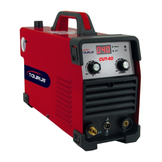
- Page 11 2. Appearance Diagram CUT- 40 Panel: LED display: Shows real-time current output and values during parameter settings. Post-flow adjustment knob: Rotate to adjust the post-flow time. Cutting torch control socket: Connects the control line of the cutting torch switch. Air and electric hybrid socket: Connects to the air and electric plug to the cutting torch.
- Page 12 CUT- 60 Panel: LED display: Shows real-time current output and values during parameter settings. 2T/4T selection: Switch between 2t and 4T modes. Pilot arc terminal block: Connects to the pilot arc line of the cutting torch. Cutting cable coupling device (positive pole): Connects to the workpiece via the earth clamp.
-
Page 13: Working Principle
facilitate the starting process and extend the life of the cutter nozzle. Selection of the 'Cut' mode allows normal cutting. Cutting torch control socket: Connects the control line of the cutting torch switch. Air and electric hybrid socket: Connects to the air and electric plug to the cutting torch. - Page 14 windy environment be unavoidable, suitable screening should be installed. 1.4 In order to allow for efficient ventilation, a clear space of at least 20cm should be allowed in front of and behind the machine as well as at least 10cm at each side. 2.
- Page 15 3.6. The connection screws on the terminal block must be tight ensuring a solid connection between the machine cable wires and the main power supply. 3.7. The correct wiring procedure is explained in the following diagram: Wiring of Single-phase AC, 50/60Hz Cutting Machine Item Item Power cord...
-
Page 16: Brief Procedure For Cutting Operation
Item Item Cutting machine Terminal block Power cord Electric control box Live wire L1 Earth wire terminal block Live wire L2 Earth wire Brief Procedure for Cutting Operation 1. Before Cutting 1.1. Wear the necessary and approved personal protective equipment (PPE) required for the task: Such as helmet, mask, goggles, earplugs, protective clothing, gloves and insulating shoes. -
Page 17: Maintenance
the rear panel of the machine. Then switch off the power at the main distribution box. 2. Schematic Diagram of Cutting Machine Item Item Cutting power supply Earth clamp Air pressure reducing valve Workpiece Air compressor Torch Maintenance Safe operation of the machine is dependent on regular maintenance and the replacement of worn and defective parts where necessary. -
Page 18: Common Machine Malfunctions And Solutions
2. Three to Six Monthly Check List Remove the side cover plate and clean off all parts with dry compressed air. Since the effective cooling of the machine is dependent on a designed air flow pattern, it is important to return the side cover plate after the cleaning operation. Not paying attention to this detail, will result in over-heating of and consequent damage to the transformer and semi-conductor parts. - Page 19 2. Common Machine Problems and Troubleshooting Problem Root cause What to do Power switch turned off or Repair or replace the damaged. power switch. Power supply phase Check power input for missing. phase loss. The "machine-on" light not lit. No No power in the grid.
- Page 20 Problem Root cause What to do The "machine-on" Arc ignition coil primary Fasten the connecting light is lit. Digital wire has poor contact. wire. display meter Remove the oxide film on Oxidation of spark gap or functional and fan spark gap surface and/or spark gap too great.
- Page 21 Problem Root cause What to do Fan, digital Poor interface contact of Fasten the pilot arc wire display meter pilot arc wire on torch. connection. and solenoid Poor connection Check and re-tighten the valve connecting wire inside the connecting wire inside operational.
Need help?
Do you have a question about the CUT-40 and is the answer not in the manual?
Questions and answers