
Related Manuals for Taurus MIG 280 PLUS


Summary of Contents for Taurus MIG 280 PLUS
- Page 1 Digital Inverter Pulsed Gas Metal Arc Welding Machine MIG 280 PLUS Operation Manual Read this manual carefully before installing, operating and maintaining the machine.
- Page 2 Description: This machine is designed and built to weld ferrous and non-ferrous metals. Disclaimer: The information, illustrations and instructions described in this manual are based on the latest product information available at the time of publication. The manufacturer and distributors reserve the right to modify the contents of this manual at any time.
-
Page 3: Table Of Contents
CONTENTS Safety Precautions ................. 3 Warnings ..................4 Packaging and Transportation ............... 7 Parameters ..................... 8 Product Description ................8 Working Principle .................. 16 Installation and Wiring ................17 Brief Procedure for Welding Operation ..........27 Maintenance ..................30 Common Machine Malfunctions and Solutions ........30 - 2 -... -
Page 4: Safety Precautions
Safety Precautions The equipment is designed for use by qualified personnel who have completed professional training and have obtained a qualification certificate as a welder/cutter. The operator shall have sufficient professional knowledge of welding, cutting and circuitry. The machine should be operated only after having read and fully understood all the safety precautions and warnings contained in this manual and those generally applicable to welding operations. -
Page 5: Warnings
Warnings Welding and cutting operations are specialised operations which present a certain degree of risk. Professional training, correct operating procedures and protective measures reduce the accident risk and damage to equipment. Personal Safety Protection Welding and cutting operations generate noise, bright light and high-temperature sparks which will cause harm to human hearing, eyes and skin unless personal protective measures are implemented and proper operational instructions are adhered to. - Page 6 Welding and cutting on sealed gas tanks will cause explosions. These operations are prohibited. Welding and cutting areas must be provided with adequate fire extinguishing equipment. Regular testing for efficiency of this equipment is compulsory as is training of staff in the use of the equipment. Once the welding/cutting operation is completed, check for any high temperature spark or metal which might cause a fire and immediately dispose of it.
- Page 7 However, it would be wise to limit exposure to EMF as far as possible and the following procedures are suggested: Welders and cutters with cardiac pacemaker implants should obtain medical advice on the effects of EMF on the implant. Welders should minimise the possibility of electromagnetic field damage through the following methods.
-
Page 8: Packaging And Transportation
A pressure regulator should be installed on the gas cylinder in use in accordance with the manufacturer's operating instructions. Quick-coupling connectors must not be used and gas hose fitting should be tested for leaks. Gas cylinders must always be kept upright and chained or belted to a cylinder trolley, base, wall, post or shelf. -
Page 9: Parameters
Parameters Model MIG-280 MIG-280PLUS Parameters name Value Rated input voltage: AC380V±10% 50Hz 3PH Rated input power: 9.2kVA 9.2kVA Rated input current: Output current range: 10A~280A 10A~280A Open circuit voltage: Rated duty cycle: Efficiency: ≥85% ≥85% Wire diameter(mm): Φ0.8~1.6 Φ0.8~1.6 Gas flow rate(l/min): 5~15 5~15 Insulation grade:... - Page 10 low-alloy steel, stainless steel and copper. Aluminium welding wire (4043/5356) and 0.8mm - 1.6mm diameter steel and stainless-steel wire as well as other solid or flux- cored wires can be used. The inverter welding machines in this series are manufactured in accordance with IEC60974-1 <Arc Welding Equipment - Part 1: Welding Power Sources >, Safety Requirements for Arc Welding Equipment.
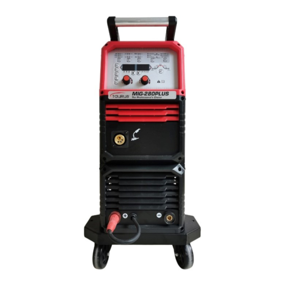
- Page 11 2. Appearance Diagram: MIG-280PLUS Control panel:Welding parameter settings and display. Euro standard torch connector:Connecting the welding torch. Gas cylinder fixed base:Accommodating the gas cylinder. Terminal sockets - positive pole (+) and negative pole (-): In MMA mode the electrode holder cable is connected to the positive terminal and the earth cable is connected to the negative terminal and should be reversed when using scratch start DC TIG in MMA mode.
- Page 12 Panel: Push-button - Welding Material:Select between AlSi, AlMg, CrNi, Fe, Cu or SP and the selected material light will be turned on. Save-button:Saves the completed welding parameters. Memory-button:Ten sets (0 - 9) of adjusted welding parameters can be recalled and saved during each operation. Wire-feed-button: Press and hold the feed button to start the wire feed.
- Page 13 Push-button - Select from parameters:When welding type is selected as double pulse, selected as 'double pulse', short-pressing this key will adjust the corresponding value of frequency/ duty cycle/ amplitude when the relevant light is lit. When Spot is selected under mode operation short-pressing this key will adjust the welding time.
- Page 14 t3~t4: Trigger released. Wire feeding stops and current drops to zero. Post- flow gas will continue for a short period. Note: the gas pre-flow and post-flow not adjustable in T2 mode. 3.2. 4T Mode This mode is suited for longer spell welding operations and entail the following: arc start current, preset current, arc-stop current.
- Page 15 3.3. Spot-welding Mode In this mode, welding time can be preset and the diagram below depicts the activity: 0~t1: Press torch trigger. Gas pre-flow starts. t1~t2: Wire feed starts and gas flows. t2: Welding starts and the welding current reaches the preset value. t3: Trigger released within the preset welding time, wire feed stops immediately and the current drops to zero.
- Page 16 4. Auxiliary Welding Parameter Settings Moving the menu button will allow selection of different parameters when the relevant light is lit. Parameters Default Adjustable range Pre-flow 0.1s 0.1s~5s Ignition current 100A 20A~280A Up slope 0.1s 0s~14.9s Down slope 0.1s 0s~14.9s Finish current 100A 20A~280A...
-
Page 17: Working Principle
Working Principle 1. Three Ways to Connect the Polarity Reversal Cable 1.1. General Connection(Welding Mode: Pulse/double pulse) 1.2. Flux-cored Welding(Welding Mode: MIG/MAG): 1.3. MMA Welding(Welding Mode: MMA): 2. Diagram Explaining Working Principle 2.1. A bridge rectifier converts AC to DC; 2.2. -
Page 18: Installation And Wiring
meet the welding requirements; 2.4. The in-time protection circuit provides signals to the PWM warning for overheat and over-current situations; 2.5. The closed-loop control method is adopted to make the welding power source have good anti-grid fluctuation ability and excellent welding performance. Installation and Wiring 1. - Page 19 3. Main Power Supply Connection Pay attention to prevent electric Wear goggles shock Warning: Take note of the following when the welding machine is connected to the main power supply: 3.1. The connection must be carried out by a qualified electrician or technician. 3.2.
- Page 20 Item Item Power cord Terminal block Live wire L1 Overcurrent protection device Live wire L2 Live wire L3 Earth wire terminal block Earth wire Electric control box 4. Gas-cylinder Connection Prevent gas Explosion hazard Wear goggles inhalation Warning: The following safety instructions are important when connecting a gas cylinder to the welding machine.
- Page 21 Item Item Cylinder valve cover Gas inlet Cylinder valve Flowrate regulating valve Gas cylinder adapter Flowmeter O ring Flowmeter outlet - 20 -...
- Page 22 5. Installation and Adjustment of Wire Spool 5.1 Installation of Wire Spool Installation of 15kg(Ø300mm)wire spool locating pin locating hole Item Item Wire spool hub shaft Hub nut Wire spool Align the locating pin on the shaft① with the locating hole on the spool②, slide the spool②...
- Page 23 on the shaft① with the locating hole on the spool③ and slide the spool③ onto the hub shaft① and fasten the hub nut⑤ as explained below in clause 5.3. 5.2. Brake Force Tension Adjustment Applying a hexagon socket wrench, adjust the screw fastener② to adjust the braking tension of the spool.
- Page 24 6. Wire Feeder 6.1. Composition Item Item Pressure regulating handle Drive roll Tensioner roller 6.2. Selection of Tensioner Roller and Drive Roll Non-groove U groove Non-groove Tensioner roller Drive roll V groove U groove knurled V groove roll: Suited for hard wires such as carbon steel and stainless steel wire.
- Page 25 Scale Table Diameter Pressure Ø0.8mm Ø1.0mm Ø1.2mm Drive roll V groove roll U groove roll Pressure scale Knurled roll The actual pressure scale to be used will be determined by the length of the torch cable, the type of welding torch and welding wire as well as wire-feeding conditions. After adjustment of the drive roll, press the tensioner roller.
- Page 26 7.1 Installation of Steel Wire Guide-tube ①Install the steel wire ②Insert the wire guide ③Set up the welding liner into the welding tube into Euro torch into the Euro torch adapter adapter 7.2. Teflon Wire Liner Installation ①Install the Teflon wire ②Set up the welding liner into the torch leaving ③Wire liner should be...
- Page 27 Installation and Adjustment of Welding Wire Prevent injuries Prevent injuries caused Wear goggles caused by wire by moving parts Take care: ! ◆ The wire speed generated by the feeder is relatively fast and safety during the installation and adjustment process is of prime importance. Never point the welding torch nozzle to a face or other body part.
-
Page 28: Brief Procedure For Welding Operation
h. In order to avoid i. Allow approximately 10 g. Reinstall the contact slipping, recheck the wire- to 15mm wire outside the tip after the wire has feeding pressure and contact tip and cut the emerged from the torch. adjust if required. excess. - Page 29 2. Welding Process When Welding Aluminium Steps Content Description Securely connect the welding torch and earth cable set to the machine. Ensure the earth clamp is connected near the welding zone. Select the suitable spool of wire and mount it over the feeder hub as explained in clause 5.1.
- Page 30 Select an appropriate welding wire. If using 4043, choose AlSi for soft aluminium wire. Select Ø1.2mm welding wire. Select single pulse mode Select 2T mode (No arc extinguish ) Adjust the current to a suitable value based according to the workpiece thickness. According to the actual position of the welding area, keep the torch tilted in a certain angle against the welding bead.
-
Page 31: Maintenance
Maintenance Safe operation of the machine is dependent on regular maintenance and the replacement of worn and defective parts where necessary. 1. Daily Precautionary Checks: 1.1. For any abnormal vibrations, sounds or odours. 1.2. For any sign of overheating on cable connections 1.3. - Page 32 1. Inspection Before Overhaul 1.1. Check if the line voltage on the three-phase power supply is within the range of 340V - 420V and, that all phases on a three-phase system are intact. 1.2. Check if the power cable as well as the earth wire is firmly connected. 1.3.
- Page 33 Problem Root Cause What to do Welding parameters do Readjust welding parameters or Unstable not match or irregular improve operation. excessive operation. spatter Badly worn contact tip. Replace contact tip. regulator damaged. Replace CO regulator regulator Broken or short-circuited Repair heating cable. does not heat heating cable.
- Page 34 3. Common Welding Imperfections and Analysis Imperfect Root Cause 1. Impure gas or insufficient gas supply. 2. Absorption of air during welding. 3. Failed preheater. 4. Poor gas shielding owing to strong wind. 5. Torch nozzle blocked by spatter. Porosity or 6.
- Page 35 Imperfect Root Cause 1. Loose or worn contact tip or too large in diameter for the wire thickness. 2. Uneven wire spool rotation: excessive wear on the groove of the drive roll and the pressure from the tensioner roller not adequate. Unstable 3.
Need help?
Do you have a question about the MIG 280 PLUS and is the answer not in the manual?
Questions and answers