Advertisement
Quick Links
Intelligent Lighting Controller
Models:
ILC-100pcb:
OEM embedded application/PCB form factor
ILC-100m:
Standalone/metal enclosure configuration
Ratings:
Input 12-48Vdc, 15 ma plus current capacity of supported LEDs
Output Rating Output voltage is identical to input, 6.67amps maximum output@12Vdc.
Description:
The ILC-100x series of LED Controllers are designed to control monochrome and tri-colored (RGB) LED lighting elements. The
ILC-100x controller can be controlled through a number of remote User Interfaces, including keypads, dry contact outputs, low-
voltage trigger outputs, local and remote Infrared control, IP (Internet Protocol), and computer based signaling sources (RS-
232C) such as those manufactured by AMX, Crestron and Elan Home Systems with RS-232-C or 0-10v interfaces.
TO BE INSTALLED AND/OR USED IN ACCORDANCE WITH APPROPRIATE ELECTRICAL CODES AND REGULATIONS
Important Information:
Carefully read the instructions appropriate for your needs.
This control must be installed by a qualified electrician.
For supply connections, use wires rated for at least 75 C.
For indoor use only.
Do not connect Low-Voltage to Line-Voltage Power.
Proper short-circuit and overload protection must be provided at the circuit breaker distribution panel. You can use up to a
20A maximum circuit breaker with adequate short-circuit breaking capacity for your installation.
Number of
Load in Amps (Watts)
Length (of typical LED
Discrete
of LED elements that
strips with 30 LED
Lighting
can be supported with
lamps per meter) that
Systems that
each ILC-100x
can be supported with
can be
each ILC-100x
individually
controlled
1
6.67 amps @12Vdc
43 ft (13 meters) per
(80 watts)
ILC-100x
2
6.67 amps @12Vdc
43 ft (13 meters) per
(80 watts)
ILC-100x
65,025
6.67 amps @12Vdc
43 ft (13 meters) per
(80 watts)
ILC-100x
Mounting Instructions
The ILC-100x comes in two versions. One is a pre-configured PCB ready to be device mounted (ILC-100pcb) and the other is
the same PCB mounted in a self-contained metal enclosure (ILC-100m). If you are utilizing the ILC-100m, please follow the
directions below:
1.
Determine a suitable mounting location for ILC-100m close to the LED elements that you wish to control.
2.
Utilize the built-in mounting ears and use appropriate screws to affix the unit to a stable surface.
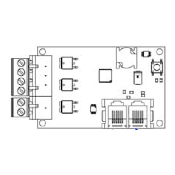
Supply (Line Input) and LED (Load Output) Wiring Instructions
DC Power Source Connections
1.
If the AC/DC power supply does not have a pre-installed 2-pin power connected
attached, strip 1/4" (6mm) of insulation from DC power cord.
2.
Connect wires as shown in Figure 1
LED Connection Block
1.
If the interconnect wire furnished with your LED strip does not have a pre-installed 4-
pin power connected attached, strip 1/4" (6mm) of insulation from DC power cord.
2.
Connect these wires as shown below:
Pin 1 (left position on connector)—BLUE LED LEAD (-)
Pin 2—RED LED LEAD (-)
Pin 3—GREEN LED LEAD (-)
Figure 1
Pin 4—COMMON LEAD (+) COMMON ANODE
User Control Wiring and Setup Instruction
In order to control the ILC-100x, a User Interface needs to be connected. Please refer to the appropriate section below for the
particular interface wiring and setup instructions.
TM
(ILC-100)
Total Length than
Recommended Power
can be supported
Supply for System
with configuration
43 ft (13 meters)
80 watts @12Vdc
86 ft (26 meters)
80 watts @12Vdc per ILC-
100x
529 miles (851 km)
80 watts @12Vdc per ILC-
100x
The ILC-100x series of Controllers as well as intelligent controllers manufactured by Converging Systems implement a
sophisticated bus architecture (i.e. the CS-Bus) that permits reliable communication using CAT5 wiring, without the need for
repeaters, on wiring runs up to 4000 feet. There are two communication ports on each ILC-100-- one socket is a Powered
connector (Port 0) which provides DC power to connected Interface Devices while the other socket (Port 1) is an Unpowered
connector which does not provide external power to other devices but is designed to relay communication data from one ILC
device to another. It is important that proper wiring convention is used when connecting one or more devices. See the
appropriate section below for more information here.
CS-Bus RJ-12 Connector)
(LEFT or "OUTPUT" PORT 0)
(see Figure 2
#1 (left) IR
#2 GND
#3 485-
#4 485+
#5 5V DC (regulated)
#6 9V DC (unregulated)
Important:
Figure 2
Note: If multiple ILC-100x controllers (lighting controllers) or if multiple IMC-100 controllers (motor controllers) are required for
the installation or if one or more User Control Modules (i.e. keypads, serial adapters, IR receivers, Internet Adapters, etc.) are
required for control purposes, communication wire needs to be utilized between the above components in order to enable
operation. For more information, see the ILC Installation Manual or the IMC Installation Manual for more information here.
Keypad (BSKP-2110L) -- "Intelligent 11-button Keypad for Lighting Control"
The BKSP-2110 is a CS-BUS compatible intelligent keypad that can be used to control the Hue, Saturation and Lightness of any
shade of color. In addition, the keypad allows up to 6 presets to be stored and recalled and enables a particular light setting to be
turned OFF and ON with a simple push of a button. Finally, a highly sensitive IR receiver is built into the front of the device so
that a supported IR handheld device can be supported as well.
1. Create a straight-thru 6 connector cable with RJ-25 (6P6C) connectors on both
ends. CAT5 wire should be used for longer runs (over 10 feet) while flat phone
wire can be used for shorter runs. For CAT5 installations, maintain twisted pairs
for pins 1/6, pins 2/5 and pins 3/4.
2. Plug one end of the communication cable into the back of the BSKP-2110L and
the other into Port 0 of the ILC-100.
Note: If you plug the communication cable into Port 1 on the ILC-100, no power will
be provided to the BSKP-2110L and the keypad will not operate.
Intelligent Bus Translator (IBT-100) -- "RS-232c to CS-Bus Adapter/Firewall"
TM
The Intelligent Bus Translator (IBT
) is a robust standalone RS-232-C serial interface converter/firewall for CS-BUS and other
TM
RS-485 devices. The IBT-100
is designed to provide the highest degree of circuit protection, isolation and remote connectivity
for interconnected equipment. The CS-BUS (based upon the hardware specifications of RS-485) forms the communication
backbone for a number of Converging Systems' controller devices including the BRIC and the IMC-100
controllers.
1. Create a straight-thru 6 connector cable with RJ-25 (6P6C) connectors on both
ends. Maintain twisted pairs for pins 1/6, pins 2/5 and pins 3/4.
2. Plug one end of the communication cable into the back of the IBT-100
other into Port 0 of the ILC-100.
Note: If you plug the communication cable into Port 1 on the ILC-100, no power will
be provided to the BSKP-2110L and it will not operate.
Infrared Keypad (ILC-IR-10W1) -- "Handheld IR 10 Button Keypad for Lighting Control"
The ILC-IR-10WI is an infrared remote device customized to control the ILC-100x family of lighting controllers. It requires a
programmed IR receiver such that exists on the BSKP-2110L or other BSKP keypads. In addition, it is compatible with the
standalone IR-EYE (IMC-RIR).
Warning: Typical 3-wire IR receivers available from Xantech are not compatible. You will damage your unit if you connect these
types of devices. Your warranty will be void if it is determined that you have used these types of devices.
Wiring Pinouts
CS-Bus RJ-12 Connector)
(RIGHT or "INPUT" PORT 1)
(see Figure 2
#1 (left) IR
#2 GND
#3 485-
#4 485+
#5 No connect
#6 No connect
For CAT5 installations, maintain twisted pairs for pins 1/6,
pins 2/5 and pins 3/4.
Keypad Wiring
TM
intelligent motor
IBT Wiring
TM
and the
Advertisement

Related Manuals for Converging Systems ILC-100 Series

Summary of Contents for Converging Systems ILC-100 Series
- Page 1 The ILC-100x series of Controllers as well as intelligent controllers manufactured by Converging Systems implement a Intelligent Lighting Controller (ILC-100) sophisticated bus architecture (i.e. the CS-Bus) that permits reliable communication using CAT5 wiring, without the need for repeaters, on wiring runs up to 4000 feet. There are two communication ports on each ILC-100-- one socket is a Powered...
- Page 2 If you see this pattern, you have confirmed the proper operation of your ILC-100 system. User Interface Device Action © Converging Systems. 2011. All Rights Reserved. Version 1.2 Printed in USA. Converging Systems, IMC-100™ , ILC and e- BSKP-2110L Keypad Depress the *(star) button Node™...
Need help?
Do you have a question about the ILC-100 Series and is the answer not in the manual?
Questions and answers