
Related Manuals for Velleman DWH G955


Summary of Contents for Velleman DWH G955
- Page 1 DWH SERIES VIDEO SECURITY SYSTEM Installation and Operation Instruction Manual Model: G955 Version 1.0 DRAFT This manual should be retained for future reference...
-
Page 2: Table Of Contents
CONTENTS IMPORTANT NOTICE.......................3 PLEASE READ BEFORE YOU START...............3 WIRELESS DEVICES OPERATING RANGE ............3 IMPORTANT SAFETY PRECAUTIONS .............3 REQUIREMENTS FOR REMOTE VIEW..............5 KIT CONTENT ........................6 SAFETY AND INSTALLATION TIPS................7 Camera Installation.....................8 Setting the Camera Channel (optional) ..............9 Pairing the Camera to Receiver (optional) ..............9 QUICK START GUIDE....................10 Set Up the Camera....................10 Set up the Wireless Touch Screen Monitor ..............10... - Page 3 Time .........................29 Clock Alarm ......................29 Time Setting ......................30 Timer ........................30 Storage Management ....................31 Format ........................31 Overwrite........................32 System Upgrade .......................32 Language ........................33 Quick Tips ........................33 REMOTE ACCESS ......................34 Overview ........................34 Downloading Android APP..................34 Downloading iPhone APP..................34 Connecting to the Internet ..................34 MAINTAINING YOUR SYSTEM ...................36 TROUBLE SHOOTING....................37 PRODUCT SPECIFICATION ..................38...
-
Page 4: Important Notice
IMPORTANT NOTICE PLEASE READ BEFORE YOU START Always use discretion when installing CCTV equipment, especially when there is perceived policy. Enquire relevant local regulations applicable to the lawful installation of video recording/surveillance. Third party consent may be required. WIRELESS DEVICES OPERATING RANGE Ensure the signal reception viewed from the wireless camera(s) is the best possible reception between the camera(s) and receiver. - Page 5 FCC Compliance Statement: This Products with CE Marking comply with device complies with Part 15 of the EMC Directive (2004/108/EC); Low FCC rules. Operation is subjected Voltage Directive (73/23/EEC); to the following two conditions: R&TTE(1999/5/EC); ROHS Directive (1) this device may not cause harmful interference, (2011/65/EU) issued by the Commission of the and (2) this device must accept any interference European Community.
-
Page 6: Requirements For Remote View
System “Device ID” and “Password” are provided on a label applied at the back of the LCD Monitor (behind the pull out stand). The “Device ID” and “Password” are needed for remote viewing. For security purpose, it is recommenced for user to copy the “Device ID” and “Password”... -
Page 7: Kit Content
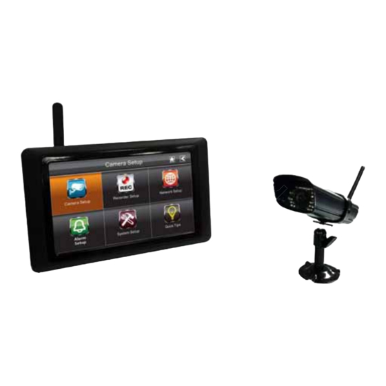
KIT CONTENT Wireless Camera w/ stand Wireless Touch Screen LCD Monitor x 1 Camera Antenna x 1 5V/1A Power Adapter x2 Internet Cable x 1 Screw Bag x 1 Instruction Manual x 1 Tools Required: Electric drill 5mm masonry drill bit 15mm masonry drill bit No. -
Page 8: Safety And Installation Tips
SAFETY AND INSTALLATION TIPS LCD Touch Screen Monitor keep away from heat sources and high temperature places Avoid direct sunlight Avoid humid places Avoid vibration Install in a ventilated environment The supplied SD card can be replaced with up to a 32GB SD card if required Installation Notes Always follow manufacturer’s advice when using power tools, steps, ladders, etc and wear protective equipment (e.g, safety goggles and gloves) when drilling holes, etc. -
Page 9: Camera Installation
Camera Installation Avoid positioning the camera so that it is facing directly at the sun as this will impair the picture quality viewed. Avoid pointing the camera lens directly through clear glass as the night vision LEDs will cause a blurred image at night. Avoid pointing the camera directly at any bushes, tree branches or moving objects that might naturally move due to winds. -
Page 10: Setting The Camera Channel (Optional)
Setting the Camera Channel (optional) The wireless camera supplied preset to channel 1. Camera Setup section The monitor supports up to 4 cameras. Follow the steps below in setup or change the monitor channel of the camera. If you are adding another camera to link with the supplied monitor in this kit, then ensure its channel is set to a different channel to the existing camera(s). -
Page 11: Quick Start Guide
QUICK START GUIDE For further details on the installation of the camera bracket and fixings, please refer to the Camera Installation section. Set Up the Camera the Wireless Touch Screen Monitor Flip out the stand, extend the antenna, connect AC/DC adapter to the input on the side of the monitor. -
Page 12: System Operation
The monitor is fitted with a rechargeable battery and can operate for up to 2 hours on battery power once fully charged (w/Power Saving function activated). The monitor can be carried around anywhere within operating range of the camera(s), but should be used in a dry environment as it is not weatherproof. - Page 13 GETTING TO KNOW THE MONITOR AND CAMERA Receiver Receiver (Front view) (back/side) Antenna Power On/Of Pull-Out Stand SD slot Reset Button AC Power Connection Data Cable Connection WHAT THE LIGHTS MEAN Light State What it means The camera is on. (Red) Power status The camera is off.
-
Page 14: System Introduction
SYSTEM INTRODUCTION Your monitor’s system software operates through a series of screens that let you choose groups of operations. For example, when you tap on the camera icon in the Pop-up menu, you can set how you want the main viewing screen, “the Live screen” to display images from the paired cameras. - Page 15 ICON WHAT THE ICON MEANS Select how you want the Live screen to display camera input: Scan between cameras (5 seconds) Camera Mode Quad view (all paired cameras display) Full view (1 camera displays on full screen) Volume Adjust the volume level. Access the system software operation and setting page or view recorded System Settings events.
-
Page 16: Live Screen Displays
Live Screen Displays The Live screen displays in 2 views - Quad View or Full View. Quad View displays the images in 4 quadrants (only display camera that is ON). Tap a quadrant to display single camera view / full view. Tap on that image again to return to Quad View. Zoom Feature To zoom into a particular area, 1. -
Page 17: Playing Back Recorded Video
Playing Back Recorded Video From the pop-up menu, tap the following The Record List screen displays: icons Tap on the highlighted day containing the recording you want to view. The Record List screen will display that day’s recordings listed in a folder. If you tap on a day that is not highlighted, a folder displays with no recordings listed. -
Page 18: System Menu
SYSTEM MENU From the pop-up menu, tap the following The Main Screen displays: icons The SYSTEM MENU highlights the Camera Setup option as the default. Main Screen Sub Screens What it Does Camera Setup Camera Setup Pairs new cameras to the receiver. Camera on Makes the cameras visible to the monitor. -
Page 19: System Operation
SYSTEM OPERATION Camera Setup Screen Tap on camera setup. This screen should display: Camera Pairing Your camera is paired to the monitor at the factory to channel 1. To add new camera(s) to your system, you have to pair it to the different channel(s). From the pop-up menu, tap the following The Main Screen displays: icons... -
Page 20: Camera Activation
Camera Activation When you add a camera to your system, the system will turn on the camera automatically. From the pop-up menu, tap the following The screen displays: icons An X indicates a camera is OFF, a check indicates ON. Tap on the camera to turn it ON or OFF. -
Page 21: Recorder Setup Screen
Recorder Setup Screen Motion Detection From the pop-up menu, tap the following The screen displays: icons Tap the camera’s to set the sensitivity to Off, Low or High. Default = low. The screen will return to the Motion Detection screen after 10 seconds or when you press the Back icon. - Page 22 The incoming mail server (Email To) receives the email notification sent from the SMTP server, The user must be able to receive email on a Windows PC or on mobile devices (such as an iPhone, iPad or Android smartphone or tablet) to receive e-mail alerts from the system.
-
Page 23: Schedule Record
accepted by the system. The incoming email account can be different from the outgoing email account. 6. Tap OK to save the settings, then tap to return to the previous screen. If you are using Gmail as the outgoing SMTP server, check SSL and use the data in the following table: For Gmail SMTP Server... -
Page 24: Clear A Scheduled Recording
Tap on the date you want the recording. The previous screen displays. Set up the recording and then tap Save. You can select another recording session to schedule. Clear a Scheduled Recording Access the Schedule Record screen. Tap on the scheduled recording you want to clear (1-5). The screen displays the settings for that schedule. -
Page 25: Internet Setup
Internet Setup Tap Internet Setup icon to display the Internet Setup screen. Tap on your selection and fill in the fields requested. Tap OK. Tap OK at the system reboot prompt. The Network Setup screen displays. Security Code Set up your security code to limit who can have access to the system from a remote location. -
Page 26: Network Information
If you have previously entered a code, the screen will display your current code Tap on the change code field, a key board screen displays. Enter your security code. Tap OK. The system will return to Network Setup screen. Note: Security code must be entered to gain remote access. -
Page 27: Alarm Setup Screen
Alarm Setup Screen From the Alarm Setup screen, you can: Set the length of time the alarm sounds Select a melody for the alarm. Period This selection allows you to select the alarm/siren duration for Clock Alarm and Timer. Tap Period. The Set Siren Duration screen displays. Select the alarm duration time required Tap the BACK arrow to return to the previous screen. -
Page 28: Melody
Melody This selection allows you to select a melody for the siren. 1. Tap Melody. The Change Siren Melody screen displays. 2. Select the melody required 3. Tap the BACK arrow to return to the previous screen. System Setup Screen Power Saving In Power Saving mode, the monitor will shut off LCD after idle for 2 minutes. -
Page 29: Screen Auto Lock
1. Tap Power Saving Enable to activate power saving. Default is off. A check mark appears on your selection. Tap the BACK arrow to return to the previous screen. Screen Auto Lock In Auto Lock mode, the monitor will enter screen lock mode after it has been idle for 2 minutes. -
Page 30: Time
Time The Time screen lets you set up clock alarms, set the system time, and set a timer. From the pop-up menu, tap the following The screen displays: icons Clock Alarm This feature operates as an independent alarm clock. It does not affect the operation of live video or recording video. -
Page 31: Time Setting
Time Setting This screen contains fields to set the Month, Day, Year, Hour, Minute and AM/PM. to display the Time Setting screen. 2. Tap on each field to set it. The UP/DOWN arrows shift to that field. Use UP/DOWN to set the field. 3. -
Page 32: Storage Management
2. Tap on each field to set it. Use UP/DOWN to set the field. 3. Tap START to begin the time. When the time reaches 00:00, an alarm beeps until you tap OK. Storage Management The Storage Management screen lets you format the SD card or set up the SD card overwrite function. -
Page 33: Overwrite
Overwrite This feature will overwrite the oldest files when the capacity of SD card is full. Turning on this feature will enable the system to start overwriting the oldest 300Mb files when the available capacity is less than 100Mb. From the pop-up menu, tap the following The Format Storage screen displays: icons Tap on the Overwrite feature. -
Page 34: Language
Language English is the default language. If you change the language, all system settings default to the original factory settings. You will have to reenter any specialized settings. From the pop-up menu, tap the following The screen displays: icons Select the language required. The Restore Default Settings screen displays. Tap OK to continue. -
Page 35: Remote Access
REMOTE ACCESS Overview This DWH Series Video Security System lets you view live video from your iPhone, iPad, or Android smartphone or tablet. Free apps are available through the iTunes App Store or the Android Market. Up to 2 remote users can access live video at the same time as long as they have the User ID (DID) code and security code. - Page 36 Tap Connect. The Internet Connection Status Indicator appears on the upper left of the Live screen indicating that the system is connected to the internet. You can now view live video through your mobile devices. >> While the system is connected to the internet, the LIVE screen display rate may reduce to 2 - 3 frames per second.
-
Page 37: Maintaining Your System
MAINTAINING YOUR SYSTEM Please make sure to upgrade your system firmware to the latest version. Check your system firmware version on the Network Information screen (please refer to the Network Information section). Go to vendor website to check the current firmware version. Compare it with your system firmware version. -
Page 38: Trouble Shooting
TROUBLE SHOOTING TROUBLE SOLUTIONS No image Screen lock may be on. Tap the Power button to unlock the screen. Make sure the camera is power on. Make sure the monitor has enough charge / connect it to AC/DC adaptor. Move the camera closer to the monitor; it might be out of range or flip the antenna of the receiver to obtain best possible reception. -
Page 39: Product Specification
PRODUCT SPECIFICATION Camera Receiver Maximum channels Communication Range 150 meters in open space LCD Monitor Resolution 800 x 480 Camera Resolution Single Camera: 480x272 / Multiple Camera: 320x240 Operating Temperature -10 C ~ 50 C Operating Voltage DC 5V / 1A Current Consumption 500mA (MAX) 800mA (MAX) - Page 40 FCC NOTE: This device complies with Part 15 of the FCC Rules. Operation is subject to the following two conditions: (1) this device may not cause harmful interference, and (2) this devi ce must accept any interference received, including interference that may cause undesired operation. THE MANUFACTURER IS NOT RESP ONSIBLE FOR ANY RADIO OR TV...
Need help?
Do you have a question about the DWH G955 and is the answer not in the manual?
Questions and answers